
Software apps and online services | ||||||
_4YUDWziWQ8.png?auto=compress%2Cformat&w=48&h=48&fit=fill&bg=ffffff) |
| |||||
Hand tools and fabrication machines | ||||||
 |
| |||||
 |
| |||||
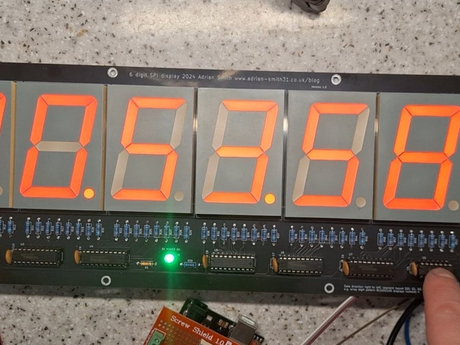
This project came to being when I wanted a large multi digit 7 segment LED display but I was only able to find MAX7219 or similar based display boards with digit heights up to 0.56″. Not being able to find what I wanted, I decided to make a 6 digit display with a standard SPI interface so it can be connected to any microcontroller with a hardware SPI interface. I also wanted to control the display brightness so I used the shift register's output enable pin to do this by connecting it to a PWM capable pin on the microcontroller I was using. In this case an Arduino Uno.
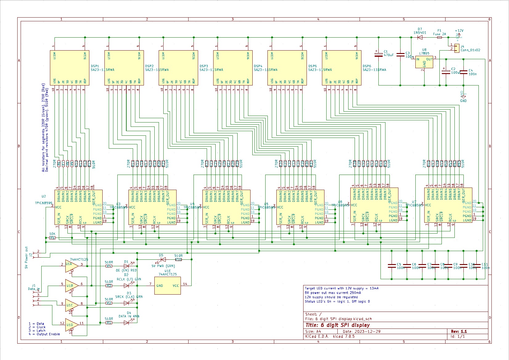
To keep costs down I decided against using external drivers with a MAX7219 and instead went with a chain of shift registers using TPIC6B595’s as their open drain outputs can sink up to 500mA (shared between all 8 outputs) and up to 50V – ideal for the large LED displays that have a forward voltage of 8.4V. The PCB would have to be powered from 12V due to the higher voltage displays so a 7805 regulator provides the 5V power for the shift registers and the input buffer which also translates 3.3V logic levels to 5V required by the shift registers.
The display PCB is suitable for electronics hobbyists and it provides indicator LED’s on the data input lines to indicate input signal status. With input signals that have a very low duty cycle the status LED’s would not light hence why ultra bright LED’s were used. Ideal for testing and development use and for use in a final, one off project. It runs off 12 volts and has an onboard regulator for the IC’s. It is compatible with 3.3V and 5V logic level inputs on the data connector.
The board was also designed with through hole components for ease of assembly and features a reverse polarity protection diode and a 5V output for powering an Arduino or similar. Current consumption with all digits and segments on is around 700mA. A 12V regulated power supply rated at 2A is needed to power this board.
I have provided the schematic and bill of materials on the attachments page so you can make your own. I may also sell a completed PCB or partially completed PCB on my blog at https://www.adrian-smith31.co.uk/blog - please take a look.


_Ujn5WoVOOu.png?auto=compress%2Cformat&w=40&h=40&fit=fillmax&bg=fff&dpr=2)
Comments