Approximately 30% of the world's carbon emissions are produced by the transport sector, of which 40% are due to individual transport. However, the solution has already been invented. Cycling is one of the most sustainable and healthy alternatives to date, but one of its disadvantages is that it is a very vulnerable vehicle. It is true that the use of bicycles in the city is becoming more and more noticeable. However, some groups decide to use other means of transport because of the lack of infrastructure or safety.
Furthermore, last year I had an accident with a car during a bike trip because I wasn't able to brake in time as I was putting back in place my water-bottle after drinking. Maybe if I had used both brakes I could have spared me some injured months. Also during the trip having cars at my back made me anxious when i fell them too close to me. In my opinion this has to be fixed to make the bicycle a much more enjoyable vehicle.
The solution this project proposes is to add an assisted braking system that complements the driving of the bicycle so that everyone, regardless of age or physical condition, can feel safe. For example, in case of an unforeseen event, lack of attention, or slow reflexes. In addition to a warning indicator of presence at the back of a bicycle which the rider might not be able to see.
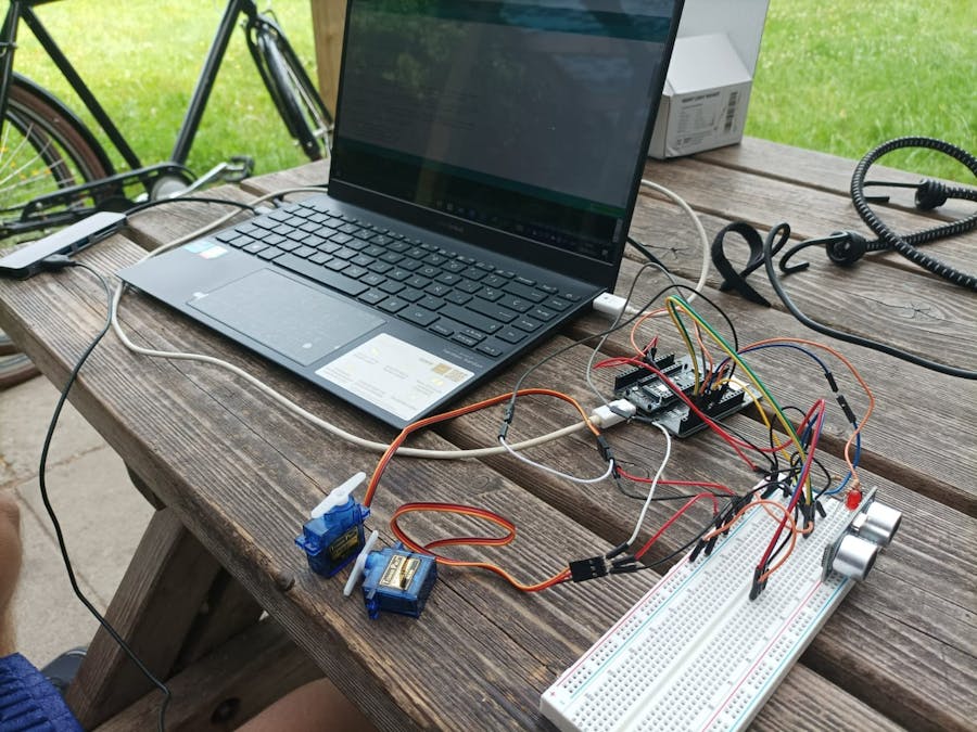
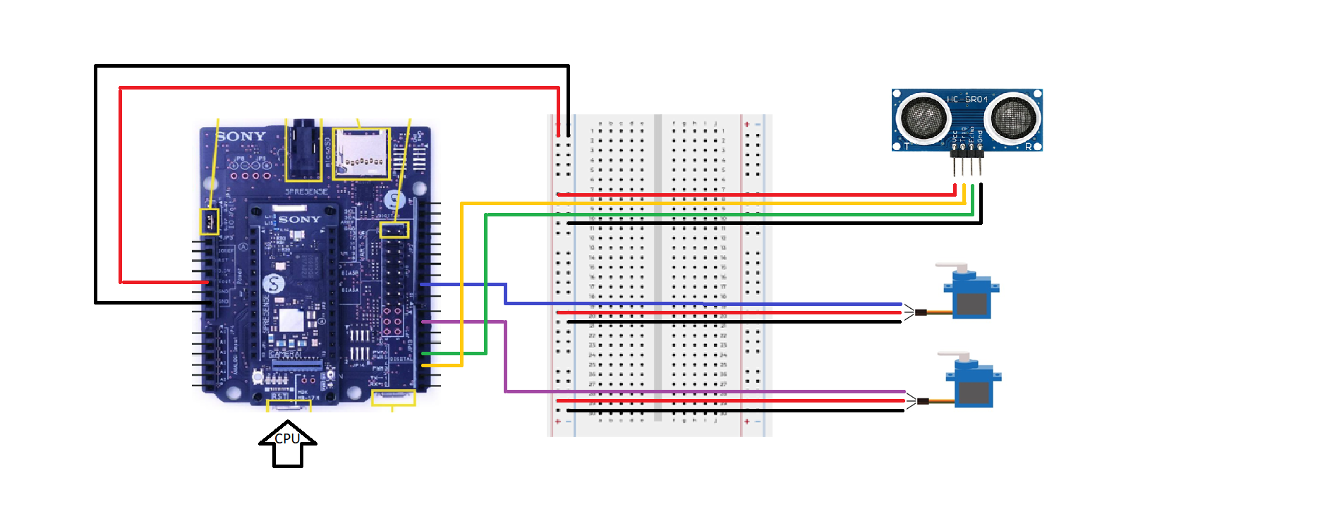
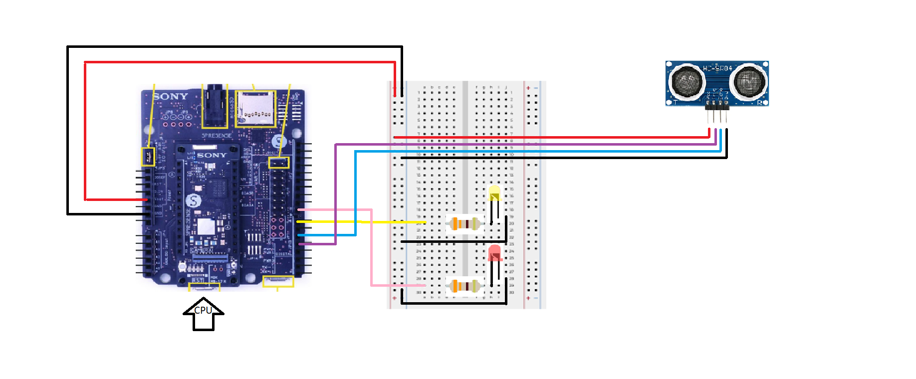
The system consists of a small electronic circuit with the Spresense technology in charge of assuring the right performance. The first part of the circuit counts with an ultrasonic sensor, and two servos in charge of assisting the braking system when a dangerous obstacle is detected ahead. And the second part constitudes another ultrasonic sensor, to measure the distance between unseen objects at the back, and two LEDs, a red one and a yellow one, to indicate if the safety measures have been compromised. This way the rider can behave accordingly and if possible avoid an accident.
Its main functionalities work like this:
https://drive.google.com/file/d/1GmoD68vfcWQbkD7TzCumJjNNWLZ4nbq7/view?usp=sharing
https://drive.google.com/file/d/1NIXOANgTyRQ111bF8hiFQ5ODbYZ5WLdc/view?usp=sharing
This project aims to offer a cheap homemade solution to enhance safety during a bicycle ride, and to promote both use of this kind of vehicles and the development of embbeded aplications. Feel free to build it by yourself and introduce your own improvements!
Thanks to hacksterio and the sony developer community for making this project possible and for all the resources and tools provided.


Comments