

Hardware components | ||||||
_ztBMuBhMHo.jpg?auto=compress%2Cformat&w=48&h=48&fit=fill&bg=ffffff) |
| × | 1 | |||
_wzec989qrF.jpg?auto=compress%2Cformat&w=48&h=48&fit=fill&bg=ffffff) |
| × | 1 | |||
_baVEVgguW1.jpg?auto=compress%2Cformat&w=48&h=48&fit=fill&bg=ffffff) |
| × | 1 | |||
| × | 1 | ||||
 |
| × | 11 | |||
| × | 3 | ||||
| × | 1 | ||||
 |
| × | 1 | |||
 |
| × | 1 | |||
 |
| × | 1 | |||
| × | 4 | ||||
| × | 1 | ||||
| × | 1 | ||||
| × | 1 | ||||
Software apps and online services | ||||||
 |
| |||||
Hand tools and fabrication machines | ||||||
| ||||||
 |
| |||||
| ||||||
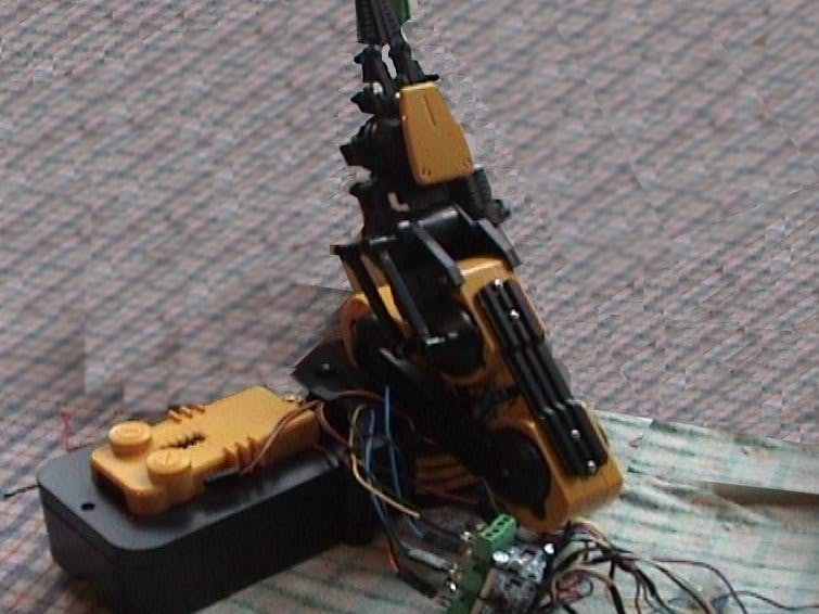
I wanted to build a control unit which worked my assembled Plastic Robot Arm kit as the exiting switches operation was manual and complicated. It also required two sets of batteries to give a positive and negative supply to the controls. This drove the motor forward or reverse by changing the current flow through the motor.
Part of this was achieved by subsuming a motor driver board with an L9110 driver chip on it, to reduce the power supply to one voltage, which could be simply supplied by a standard single polarity power supply.
The board would be capable of operating the 3v DC motors in the robot arm and will work on voltage up to 12v. It also would supply 800ma for each motor which is more than enough. It basically reverses the supply voltage on the output depending on two “Logic” inputs.
The robot arm has a total of 5 motors, plus a bright LED mounted in the jaws of the pincers.
I wanted to use the Arduino board to reduce the complicated control and allow it to be controlled easily.
Any type of Arduino board can be used, long as it has the digital outputs, 5 volt power and analogue input (for testing )available.
The HardwareI have seen a lot of projects using this L9110 dual motor board, but they have all used PWM to drive the motor, which requires both controllers to be used for one motor, which seems a waste.
What is not mentioned, as there does not seems to be a datasheet for the board, that connecting the Arduino digital outputs direct to the two control inputs does not work!
This is because the power supply voltage for the motors drives the interface, if it is a different voltage from the +5 voltage used by the Arduino, so it can kill the motor power supply or kill the Arduino!
There is no details of this in the information given by the manufacturer, but it is listed in this article.
https://www.electroschematics.com/13797/l9110-motor-driver-primer/
This explained how to do a test on the board using a three way switch to connect each control input to Ground (0 volts). This did not require the board to be disassembled, as detailed as a requirement as in other projects.
The problem was how to duplicate this using a logic IC, which could be controlled by an Arduino.
What was required was a Open Collector Output stage, where the power supply for the logic chip was not connected to the Motor board, but the output would act as the switch does, and short the logic input of the motor board to Ground.
I found a chip which was a NAND gate which had a Open Collector Output stage, which requires two HIGH inputs to operate the chip, so the output connects to Ground.
The chip number is called a 7403 type, this could come in different manufacturers with different prefixes SN, HC etc but it is all the same chip as far as this project is concerned.
The chip has four of the NAND gates built into a 14 pin DIL package, so with careful designI could control up to 2 Motors with each chip.
I built the project on stripboard, so the layout was easy, for 5 motors I needed three 7403 chips to control the motors. The LED I could control directly from the Arduino, but because it was power hungry, I decided to drive it from a Inverter gate using a 7404 chip with +5 volts, not using the motor boards.
If I had driven the motor boards direct from the Arduino I would have required 2 logic outputs from the Arduino board for each motor, 10 outputs in total. Plus another for the LED, a total of 11 Outputs.
Using the NAND gates I could reduce this down to 7 Outputs, One motor enables for each motor, one for the LED control and one for the Forward/Reverse switch. I made the decision that I would only need to operate one motor at a time, which would greatly reduce the size of the power supply! So one input to the NAND gate would turn the motor ON or OFF, plus one input for Forward or Reverse.
To Operate the board properly I could only operate one input at a time, as operating two inputs at the same time with the same output would turn off the motor. Rather than program this into a complicated program, I decided to program this into the logic chips by doubling the number of gates to control the motor to two, one for ON/OFF and Forward, and one for ON/OFF and Reverse. By using an inverter gate, I could also make sure that only one operated at a time!
So I included the 7404 chip in the design which has 6 (hex) Inverter gates in a 14 pin package. I used one for the driver of the Forward /Reverse control and two others to drive the LED. All the controls will be HIGH (+5 volts) to operate the motors and make it go forward.It also allowed the LED to light. This made it simpler for programming the Arduino.
NAND Gate OperationIf EITHER of the NAND gates inputs are LOW, the Output is HIGH, NOT operating the logic on the motor board (it does not operate the transistor at the end of the logic output).
If BOTH of the NAND gates inputs are HIGH, the Output is LOW operating the logic on the motor board (it does operate the transistor at the end of the logic output).
The inverter chip changes the output to the OPPOSITE to the input, i.e. put in a HIGH, the output is LOW and vice versa.
The complete circuit design is shown below, there are 5 motor enables, one LED enable and a forward/reverse control.
Power SuppliesThe +3v power supply for the motors is separate from the Logic supply, which is obtained from the Arduino board +5 volt supply. They all use the common zero volts supply connection, which is connected to the Arduino board and the +3v supply. The same power supply is connected to all thee motor control boards, which are stacked one on top of each other between the motor and the interface board. The Arduino is only connected to the interface board, to stop any damage!
Each interface is exactly the same, multiplied by three, one for each of the dual motor boards!
They all use the same forward/reverse signal lines and power supply. The inputs and outputs are on separate connectors.
You will need to be a good with a soldering iron.
You need to have male headers to connect to the Arduino board, 4 and 3 sets.
You will need three female headers of 6 sockets wide, one for each motor board.
You will need two, two pin male headers, one for connecting the +5v power supply to the logic board and one for connecting the two pin LED female header to the logic board.
Multi-stranded wire is used for connecting the boards to the headers and single cored wire for connecting between the components on the board.
You will need four 14 pin IC sockets and stripboard of 38 strips by 20 holes (0.1 inch spacing) to mount them on.
You will also need 10, 1K resistors to control 5 motors via the motor boards, to limit the current drawn by the logic board.
I used a two way chocolate block connector to connect up the +3v power supply, so it can be connected to two AA batteries or a mains driven power supply of the same voltage.
1. The IC sockets are sited first, bending over the pins under the board on the copper side. Solder them in place, then remove the copper track between the two sides of the IC socket.
2. Cut the tracks between the 7403 chip and the 7404 chip pins. The 7404 chip sits behind the first 7303 chip as you can see on the picture of the layout.
3. All four sockets need to be fitted with space in-between the three 7403 socket for the two 1K resistors that bring the outputs from the other side of the socket to the edge of the board.
4. Then wire from the power supply rails at the top of the board to each of the Pins 14 and 7 on each of the IC sockets.
5. Next put in the wire loops from pins 10 and 13, 2 and 4 on the 7403 chips.
6. Fit the wire loop between 4 and 5 on the 7404 chip.
7. Fit the resistors vertically from pins 1 and 6 of each 7403 on the board and cut the track between two ends, so it is not shorted out.
8. Fit the two resistors next to the IC sockets for each 7403, and then cut the copper strip between two ends.
9. Connect pin 1 of the 7404 chip to the pins 5 and 13 on all of the 7403’s. This is the Forward input.
10. Connect pin 2 of the 7404 chip to the Pins 1 and 9 on all of the 7403’s. This is the inverted version of the forward input.
11. Connect all the other wires to pins 9, 11 on the 7403 (see the circuit diagram).
12.Connect the stranded wires from headers pins 1-6 to the resistors from pins 3, 6, 9 and 11. Pins 3 and 4 go to the chocolate block from each board. An additional negative (Ground) wire from the chocolate block to the negative (0v) on the logic board.
13. Solder one of the two pin male connectors (short side) to the negative (0v) on the logic board using enough stranded wire long enough to reach the LED connector on the robot arm.
14. Solder another wire to the other pin of the male connector, but on the logic board end solder a 1K resistor.
15. Solder the other end of the resistor on to pin 6 next to the 7404 chip.
16. Next solder stranded wires from pins 2, 10 on the 7403 chips to the male header as shown in the circuit diagram.
17. Next solder stranded wires from pins 1 and 3 on the 7404 chip to the male header as shown in the circuit diagram.
18. Solder one of the two pin male connectors (short side) to the negative (0v) on the logic board using enough stranded wire long enough to reach the Gnd connector on the Arduino board.
19. Solder another wire to the other pin of the male connector, but connect it to the +5v supply on the logic board.
I used different colours to identify the wires, you need to do the same to identify any mistakes!
Please at every stage of soldering check the connections afterwards, by using a multimeter set to 'Ohms', to check if the connections are not with the pins on either side of the connection you have just made.
Use heat shrink tubing to cover the bare contacts on the IDC headers, both Male and Female.
Circuit DiagramYou need the Arduino IDE (Integrated Development Environment) which is free and downloadable from Arduino.cc), the.ino program I have written, a program called Test Motor to control the board through logic board.
You need to install the IDE program on a PC or Linux machine to transfer the program to the UNO board.
The program turns ON the motors one at a time, monitoring a switch on the analogue input on the Arduino board.
You can set the forward or reverse direction, but releasing the switch turns off the motor and reverses the direction.
You can use this to test each motor in turn, downloading it each time to the Arduino, to change the motor status.
Each one of the motor outputs are programmed into an array, including the LED.
HIGH output operates the motor or LED, HIGH on the forward/ reverse setting is FORWARD.
LOW output turns the motor or LED to OFF, LOW on the forward/ reverse setting is REVERSE.
[code]
int Motor[8] ; // Array for all motor output pins, one more than required
void setup() {
Motor[1] = 4; // Set output numbers for ports
Motor[2] = 5;
Motor[3] = 6;
Motor[4] = 7;
Motor[5] = 8;
Motor[6] = 9; // Set up port for LED on head of arm.
Motor[7] = 10; // Forward / reverse selection for ALL motors
// Switch connected to GND and A0, to locally turn off motors while testing.
pinMode(Motor[1], OUTPUT); // Open port to operate motor on Pincers Forward = In Reverse = Out
pinMode(Motor[2], OUTPUT); // Open port to operate motor Up= High Reverse = Down
pinMode(Motor[3], OUTPUT); // Open port to operate motor Forward = Forward Reverse = Backward
pinMode(Motor[4], OUTPUT); // Open port to operate motor Wrist Forward = Up Reverse = Down
pinMode(Motor[5], OUTPUT); // Open port to operate motor base Rotate Forward = Right Reverse = Left
pinMode(Motor[6], OUTPUT); // Open port to operate LED on head of Arm HIGH = ON LOW = OFF
pinMode(Motor[7], OUTPUT); // Open port for Forward / Reverse selection for ALL motors
}
void loop() {
digitalWrite(Motor[6], LOW); // Turn off LED.
if (analogRead(A0)< 1){ // switch ON
digitalWrite(Motor[1], HIGH); // Turn on Motor 1. HIGH turns it on! Pincers
digitalWrite(Motor[7], LOW); // HIGH is Forward, Reverse is OFF.
Serial.println(analogRead(A0));
}
if (analogRead(A0) > 200 ){ // switch OFF
digitalWrite(Motor[1], LOW); // Turn on Motor 1. HIGH turns it on!
digitalWrite(Motor[7], LOW); // HIGH is Forward, Reverse is OFF.
Serial.println(analogRead(A0));
}
delay(200); // debounce the switch action
}
[/code]
The commented lines start with //.
The lines in void setup() set up the digital ports used for the program.
In the void loop()section
The LED is turned OFF, all the motors should start up as OFF.
A ON/OFF switch is wired to Gnd and Analogue input (A0) on the Arduino board. Closing the switch operates the “ON” commands. Opening the switch operates the commands in the “OFF” section. This gives manual control over the motors being tested. This is not in the circuit diagram as it is only used for testing.
Having now got control over the robot arm, you can now program its movement using all 5 motors, forward or reverse from the Arduino.
As all the outputs have a pin number, you could use the “Cheap Webserver using ESP-01 and Arduino UNO” project to control this arm remotely.
You can also try PWM on the motor enable pin to slow it down and control the speed of movement.
Also the motors don’t have to be in robotic arm, they can be a car, boat, anything that runs on DC motors.


Comments