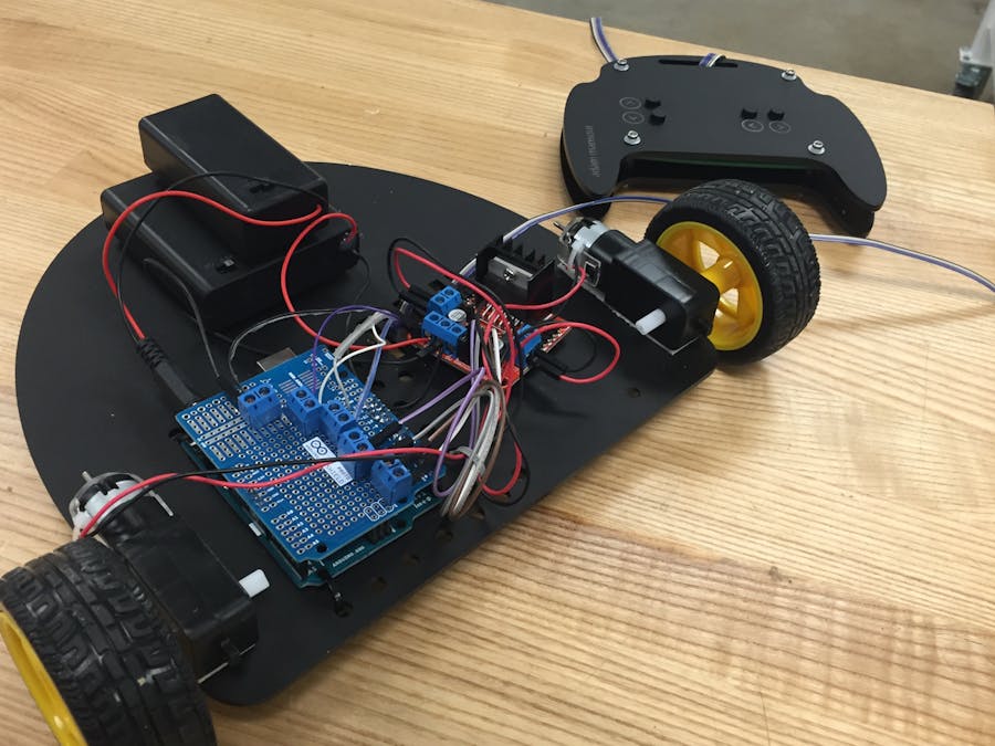
Making a remote control car
The task for this project was to make a remote control car that can:
-Travel forwards, backwards, left, and right
-Drive in a straight line for 5 ft, within a 1 ft wide space
-Park in a 16x16in square
-Go up a 3ft long x 1ft tall ramp
My first iterations can be found here:
https://www.hackster.io/adammansour/homework-6-137703?ref=user&ref_id=31424&offset=0
The first iteration of the project was structurally unsound, and overly compact for all of the components I needed to set on it (2 battery packs, an Arduino, and an H-bridge), so in this iteration, I decided to pursue a simple, large, base structure. In addition, I strayed from using a servo to control steering, and focused on using differential steering (having the two wheels turn at different speeds) to control the vehicle.
These design decisions helped simplify the device, and let me focus on making it easily maneuverable, modifiable, and structurally sound. I used acrylic to build the majority of this vehicle and its remote because of its clean look and structural rigidity.
The Base
In designing a new structure for the base, I began by thinking about how I could fit all of the aforementioned components of the device onto the car. I measured each component, and drafted each part's shapes on Illustrator, to be engraved on the bottom of the device. Next, I designed a rounded shape for the base to reduce risk of damage upon impact, as any force imparted would be spread more effectively.
Here is how it turned out (the file I printed is attached to this page):
Note that the holes around the Arduino and H-Bridge were for zip-tying the components down, and that the 6 rectangles under the H-Bridge are for looping the remote control leash through, so that any pulling of the leash imparted force on the base and not the electronics to which the leash wires will be attached. The holes at the very bottom of the base are to attach the 3D printed marble caster, which serves as the stabilizer of the vehicle, alongside the two wheels attached to the motors at the top. I used double-sided tape to attach the gear motors and wheels to the base, as shown below. I also tested to see whether the motors needed to be oriented in the same direction for the car to go straight, but in all orientations, the right motor tended to be faster than the left.
Circuitry
Next, I hooked up the circuitry of the vehicle. This consisted of an Arduino, H-Bridge, solderless breadboard, a 9V battery pack attached to the Arduino, and a 6V pack powering the motors. The motors are attached to the H-bridge as output, and the H-bridge is connected to pins on the Arduino, each controlling a different directional function of the vehicle (forward, backward, left, and right). These controls were hosted by switches on the solderless breadboard, each grounded to the Arduino, and powered by digital pins also on the Arduino. There are no resistors involved as I used the internal resistor of the Arduino, as controlled in my code (attached to this page).
Next, I began transitioning the circuitry from jumper cables plugged directly into the solderless breadboard and Arduino, to a soldered proto shield.
The Remote
For a more permanent and ergonomic solution to controlling the vehicle from a distance, I transferred the solderless breadboard of switches to a perfboard with larger switches, but the same general circuitry. Each switch is still connected to a pin on the Arduino for a different direction, as well as the ground. The wires connecting the switches to the proto shied are long, stranded wires all attached by insulation.
All of these connections are pictured below.
The layout of the remote is intended to be ergonomic, and intuitive in that forward and backward are together, controlled by the left hand, and right and left are controlled by the right hand. The buttons are spaced for comfortable holding.
Here is a rough paper prototype that helped me determine how to space the switches on the perfboard.
Here's how it turned out:
This solution, however, was far from sleek. I decided to make a casing of sorts to house the perfboard. I wanted to make a remote that would allow the car to be picked up by the remote without straining the wires, as well as one that could be comfortable to hold for a long period of time, with intuitive and clear indications of how to control the vehicle. To do so, I engraved a hole for the leash wires to loop through and engraved which direction each button corresponded to onto the remote, respectively.
The series of photos below shows my process from making paper prototypes, which I evolved to best fit the remote through rapid iterations, and ultimately fastening the laser cut remote to the perfboard with screws, washers, nuts, and laser-cut spacers.
Final Wire Attachments
Next, I looped the leash wires through the base of the vehicle, and connected them to the terminals soldered to the protoshield. These connections proved to be inconsistent, leading the car to intermittently work and stop, so I soldered the stranded wires of the leash, to solid core wires and heat shrunk them together, as shown in the pictures below.
The Final Product
Ultimately, the remote control car was successful in the criteria of the task, but it had trouble going up the ramp in the forward direction. In the future, I would add more traction to the wheels, or use 2 more motorized wheels to make the car more powerful in scaling inclines.
Here are a video and photo of how it turned out!


_ztBMuBhMHo.jpg?auto=compress%2Cformat&w=48&h=48&fit=fill&bg=ffffff)


Comments