

Part 1: Switches
In this part of the assignment, followed three examples for how to use a switch to control an LED with an Arduino, with the help of this tutorial.
Some initial challenges were:
- Making sure I was using the correct resistor, 10k vs the 330 I started with
- There was a delay in the switch response times to start, but after making sure the correct wires were aligned on the breadboard, all went smoothly
Below is a picture of the circuit I used.
Example 1: Turn on the LED when the button is pressed.
Example 2: Press button to turn on LED, press again to turn off, innocent version
Example 3:
Part 2: Creating an automaton
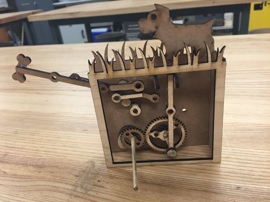
I began with the idea of having a dog chase a bone back and forth.
As I drafted the idea in Illustrator, I decided to have the bone move vertically on a cam and the dog in a circular motion, attached to a gear. There weren't any issues in laser cutting the vector file.
Once the parts were cut, I began gluing them, but found that I needed to use more spacers than anticipated in order to layer the gears and cams without overlap.
A lever that I anticipated to hold up the dog's gear attachment proved to not rotate as I expected, and introduced too much friction, so I removed it from the automaton.
As I continued to build, I found that the cam was hugely unstable, so I used extra parts from elsewhere in the design, on the upper right in the above picture, and two key-like parts to hold the dog in a vertical position as it rotates.
After much trial and error, the cam and the attached bone would not move vertically smoothly, so I decided to sand the parts down, but I still had no luck. I also tried doubling up the cam's surface area by gluing two of the same shape together, but it was still not stable enough, and perhaps too steep, for the bone to move correctly. In turn, I just left the bone to lean off the device, and remain stationary.

Comments