

Hardware components | ||||||
 |
| × | 1 | |||
| × | 1 | ||||
 |
| × | 1 | |||
Software apps and online services | ||||||
| ||||||
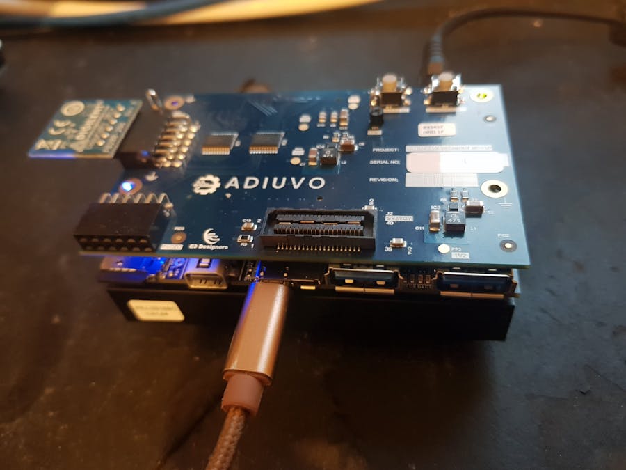
The Ultra96V2 breakout board with PMOD and ZMOD support worked well with a bare metal approach. However, to get the best flexibility, scalability and integration for projects we ideally want a PYNQ overlay which supports the PMOD interfaces.
In this project we are going to look at how we can create a PYNQ 2v6 overlay which supports the add on board PMOD interfaces using a IOP.
An IOP is a MicroBlaze subsystem which is able to work with interfaces which are provided on the PYNQ boards. Within the PYNQ environment there are three varieties of IOP which support
- PMOD
- RPI
- Arduino
The Pmod IOP provides the capability to drive a range of Pmods directly from without the need to create a new drivers etc.
To create an overlay which includes the IOP is pretty simple.
Creating the IOP TCL ScriptTo be able to use a IOP in a custom overlay the best approach is to use an existing IOP instantation as a template.
The first thing we need to do is clone the PYNQ git repo from
Once this has been cloned we need to recreate an existing base design for the Pynq Z2 base. This design contains several IOP processors from which we can extract a template script.
Open Vivado 2020.1 and change directory to PYNQ\boards\Pynq-Z2\base
From the TCL command window run the following
source build_ip.tcl
source base.tcl
Once the project has been created in the TCL window enter the following command which will write out a TCL description of the IOP Pmod.
write_bd_tcl -force - -hier_blks [get_bd_cells iop_pmoda ] iop.tclThis file can be used to recreate a IOP design in any design we desire now.
To create a new overlay for the Ultra96V2 we first need to create a new project
Select the Ultra96V2
At the end of the new project dialog click on finish
To be able to use the IOP overlay we need to add in the IP repository which was created when we ran the build_ip.tcl script.
We can do this by adding in IP repo under the settings option, the IP will be located under the PYNQ\boards\ip directory
Once the repo has been added we can clock the settings
The next step in the creation is to insert a Zynq MPSOC and configure it of the Ultra96V2 by running the Block Automation
This will configure the Ultra96V2, Clocks, interfaces and DDR as required
Once the processor has been configured correctly we can source the IOP.tcl script using the Vivado TCL console
source iop.tclRunning the script will implement a new command which will recreate the IOP in the design when executed.
We can implement the IOP in our design by running the command
create_hier_cell_iop_pmoda / pmod1This will create a single IOP Pmod in our block design, as the breakout board has 2 connectors we need tow IOPs.
Looking inside the IOP you will see the microblaze, IIC, SPI and output switch along with the necessary reset and interrupt control. This includes the ability to program the LMB BRAM from the Zynq PS.
The completed design required the following IP in addition to the IOP blocks
- MDM - MicroBlaze Debug Module
- AXI Interconnects - Establish the AXI networks for the master and slave
- Slices - Four single bit slices from the PS EMIO to provide reset and interrupt acknowledge signals. This must be named correctly
- Address Remap - Remap the address from the MB to the PS slave interface
Once these have been completed the next thing we need to do is ensure the address map of the memory of the system is correct and aligned for the PYNQ build.
Once the addresses are correct we can implement the design to obtain the bit stream and the HWH file.
Using the IOPTo use a microblaze in the PL we need a BSP to be provided to PYNQ however, there are build in BSP for the IOP Pmod. This does however mean we need to ensure PYNQ can identify correctly the IOP BSP.
See the PYNQ documentation for more information
We do this via the overlay class we create, allocating the microblaze to a PMOD type. This will allow PYQN to be able to identify the BSP correctly such that we can use it.
import pynq
from pynq import GPIO

__author__ = "Adam Taylor"
__copyright__ = "Copyright 2020, Adiuvo"
__email__ = "Adam@adiuvoengineering.com"


class AdiuvoOverlay(pynq.Overlay):
    """.
    """
    def __init__(self, bitfile, **kwargs):
        super().__init__(bitfile, **kwargs)
        if self.is_loaded():
            self.iop_pmod1.mbtype = "Pmod"
            self.iop_pmod2.mbtype = "Pmod"
            self.PMOD0 = self.iop_pmod1.mb_info
            self.PMOD1 = self.iop_pmod2.mb_info
            self.PMODA = self.PMOD0
            self.PMODB = self.PMOD1
We also need a simple initialization file
from .Adiuvo import AdiuvoOverlayWe can then upload these files along with the hardware handoff and bit files to the PYNQ file system overlay folder
With the overlay available a new notebook can be created to load the overlay and test it out
To do this we need to have a simple commands as below
from pynq.overlays.Adiuvo import AdiuvoOverlay
Overlay = AdiuvoOverlay('Adiuvo.bit')
overlay?
The overlay command will list all of the peripherals within the overlay, this will show the Pmod1 and Pmod2 MicroBlaze systems
The next step in commissioning is to try using a PMod ALS
from pynq.overlays.Adiuvo import AdiuvoOverlay
overlay = AdiuvoOverlay('Adiuvo.bit')
from pynq.lib.pmod import Pmod_ALS
als = Pmod_ALS(overlay.PMODA)
als.start_log()
als.stop_log()
log = als.get_log()
%matplotlib inline

import matplotlib.pyplot as plt
plt.plot(range(len(log)), log, 'ro')
plt.title('ALS Sensor log')
plt.axis([0, len(log), min(log), max(log)])
plt.show()
This provides a simple plot of the light intensity
Now we know how we can implement PYNQ IOP instantiations in our designs and use the to interface with Pmods. This opens up significantly the capabilities of the Ultra96V2 breakout board.


Comments