

Hardware components | ||||||
| × | 1 | ||||
 |
| × | 1 | |||
 |
| × | 1 | |||
 |
| × | 1 | |||
 |
| × | 1 | |||
| × | 1 | ||||
Software apps and online services | ||||||
| ||||||
| ||||||
The Pynq framework enables application developers to use Python to connect with and use programmable logic in Xilinx heterogeneous SoCs, such as the Zynq and Zynq MPSoC.
This allows Python developers to leverage the acceleration and real-time performance which comes with using programmable logic. In this project, we are going to create a simple control application that uses the ability of the base overlay to integrate with Pmod DAC and Ambient Light Sensor (Pmod ALS).
The application will be able to interface with these Pmod's and then run a simple PID control loop to ensure the ALS sensor always receives a defined level of illumination.
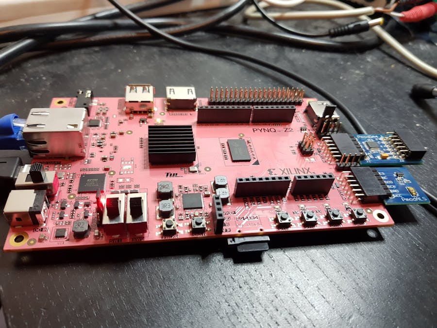
For this application, we will be using the Pynq Z2 board although any Pynq image could be used or alternatively we could create our own.
To drive the Pmods we can use the Pynq Mod package, this package allows us to interact from Python with the PmodALS and the PmodDA4.
The PmodALS will report back a number between 0 and 255 corresponding to the illumination, 0 being the lowest and 255 being the highest.
Using the Pmod package the Pmod DA4 is able to output a voltage between 0 and 2.5 volts.
Electronic CircuitTo be able to provide the illumination we need to use a Light Emitting Diode (LED). For this application we will be using a standard Red LED which have the parameters
Vf = 1.7v
Imax = 20 mA
Vf is the forward voltage, this is the minimum voltage difference between the anode and cathode for current to flow.
LEDs are current driven devices, which means the more current flowing the brighter the LED.
To enable us to control the brightness of the LED using the DAC we need to be able to convert the DAC output voltage to a variable current.
We will do this using a resistor, this resistor will be sized to allow the maximum current to flow (Imax) at the maximum output voltage (Vf)
We will use the following circuit
Thus by adjusting the output voltage we can adjust the current supplied to the LED.
Now we know the maximums we can determine the value of the resistor using the equation
In this case I will be using a 82R resistor.
When plotted this gives us the behavior as below.
When it comes to ensuring the correct light level is maintained we could just turn ON and OFF the LED as required, very fast to achieve the light level required. Although this would show over and undershoots of the light level as the design turned the LED on and off. It might also lead to anyone observing the LED to begin to feel unwell.
A better way to drive to the required ambient level is to use a Proportional Integral Derivative (PID) controller.
Opposed to just turning the LED hard ON or OFF the PID will adjust how bright the LED is until the desired output is achieved. Depending upon the tuning of the PID we may have some initial fluctuation (overshoot and undershoot) until the correct level is established or a more gradual ramp to the target illumination value.
A PID Controller is actually three separate controllers
- Proportional Controller - This controller outputs a value proportional to the current error. The output is defined as the set point (sp) minus the process variable (pv) multiplied by the Proportional constant (Kp). When the error is zero the output from the proportional controller is also zero.
- Integral Controller - This controller integrates over a number of cycles until the error value reaches zero. When the error reaches zero, it holds the previous output value.
- Derivative Controller - This controller anticipates future behavior of the error signal. its output depends upon the rate of change of the error signal multiplied by the derivative constant (Kd).
Tuning of the PID can be a little complicated, but there are a number of commonly used approaches these including Trail and Error and Zeigler-Nichols method.
In this example I used the Trial and Error approach.
Connecting the PynqThis example was configured as below, with the Pmod A connected to the DA4 and Pmod B connected to the ALS.
From the DA4 Pmod wires were used to connect to a prototyping board which holds the current limited resistor and the LED.
To get the best coupling between the LED and the ALS both need to be closely mounted together.
Within the note book the first thing we need to do is import the base overlay, download it to the programmable logic. We can then use the Pynq library to import support for the Pmod_ADC and Pmod_ALS
from pynq.overlays.base import BaseOverlay
from pynq.lib import Pmod_DAC
from pynq.lib import Pmod_ALS
ol = BaseOverlay("base.bit")
The next section of the notebook tests the Pmods can be communicated with properly. This will turn on the LED to is maximum value and read from the ALS
dac = Pmod_DAC(ol.PMODA)
my_als = Pmod_ALS(ol.PMODB)
dac.write(2.5)
illum = my_als.read()
print(illum)
One we are happy the ALS and DAC work correctly we can implement the algorithm.
The set point for the ALS can be changed as desired in the main loop
import time
import numpy as np
import matplotlib.pyplot as plt
error = 0
kp = 4
ki = 0
kd = 0.1
i = 0
d = 0
integral = 0
derivative = 0
samples = []
light =[]
prev_op = 0
dac.write(0.0)
while True:
   pv_prev = illum
   illum = my_als.read()
   i_prev = integral
   d_prev = derivative
   setpoint = 100
   error_prev = error
   error = setpoint - illum
   integral = error + i_prev
   derivative = error - error_prev
   p = kp * error
   i = ki * integral
   d = kd * derivative
   result = p+i+d
   op = prev_op + (result * 0.2)
   prev_op = op
   drive = illum  + op
   pmod_op = (op/100)
   samples.append(pmod_op)
   light.append(illum)
   dac.write( pmod_op)
   time.sleep(5)
Once we have the algorithm running we should be able see the LED adjusting its illumination as the algorithm tries to achieve the set point.
However it is always good to visualise the illumination and LED voltage drive. For this I use matlib plot to the LED Voltage and Illumination stored by the algorithm.
%matplotlib inline
X = np.arange(len(samples))
fig, ax1 = plt.subplots()
color = 'tab:red'
ax1.set_xlabel('time (s)')
ax1.set_ylabel('LED Voltage', color=color)
ax1.plot(X,samples , color=color)
ax1.tick_params(axis='y', labelcolor=color)
ax2 = ax1.twinx()  # instantiate a second axes that shares the same x-axis
color = 'tab:blue'
ax2.set_ylabel('Illumination', color=color)  # we already handled the x-label with ax1
ax2.plot(X, light, color=color)
ax2.tick_params(axis='y', labelcolor=color)
fig.tight_layout()  # otherwise the right y-label is slightly clipped
plt.show()
To test the algorithm I tried a number of different set points
Set point = 50
Set point = 75
Set Point = 100
The video below shows the LED driving to the desired set point
Of course in the presence of an additional light source the LED should adjust its brightness.
For this example I used a torch (flashlight) to change the ALS sensor reading, as you can see in the plotted data below. When the external illumination source is used the ALS sensor value goes above the set point and the LED voltage turns off.
Once the external light source is removed the algorithm recovers and drives the LED to the correct value to achieve the set point again.
While a simple project this shows how we can use the Pynq framework to create control structures which leverage the programmable logic for interfacing or acceleration.
See previous projects here.
Additional Information on Xilinx FPGA / SoC Development can be found weekly on MicroZed Chronicles.


Comments