

Hardware components | ||||||
 |
| × | 1 | |||
| × | 1 | ||||
 |
| × | 1 | |||
The DS1307 is real time clock (RTC) with plus 56 bytes of NV SRAM. Address and data are transferred serially through an I2C bus. Additional functionality is programmable Square-Wave output signal. You can set four frequency (1Hz, 4kHz, 8kHz, 32kHz) on the SQW/OUT pin.
Download library RTC_DS1307 for Arduino IDE
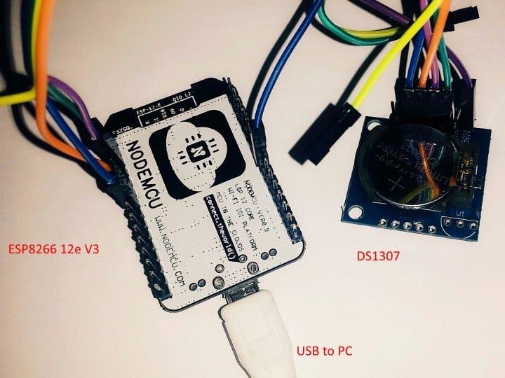
Step 1: Components- ESP8266 12e V3
- DS1307
- Few wires
1 / 4
To set the frequency, use this function:
- rtc.SQW( f1hz );
- rtc.SQW( f4096hz );
- rtc.SQW( f8192hz );
- rtc.SQW( f32768hz );
#include "ESP8266WiFi.h"	#include "Wire.h"
	#include "RTC_DS1307.h"

	RTC_DS1307 rtc;

	void setup() {
	  Serial.begin(115200);
	  Serial.println("");
	  Serial.println("START");

	  Wire.begin();

	  rtc.SQW( f32768hz );
	}

	void loop() {
	}
//byte second, byte minute, byte hour, byte dayOfWeek, byte dayOfMonth, byte month, byte year
Setting the time on DS1307:
rtc.SetTime( 00, 40, 13, 1, 06, 03, 17 );
In the loop, we will read time from DS1307:
void loop() {  //Read time from DS1307 and display (You must be connected to the serial port to see results)
  rtc.DisplayTime();
  //Convert time to unix timestamp
  long uts = rtc.UnixTimestamp();
  Serial.println( uts );
  delay(1000);
}
DS1307 has 56 bytes of NV SRAM for general use. For example, you can store configuration data.
In our case, we write and read String.
void setup() {  Serial.begin(115200);
  Serial.println("");
  Serial.println("START");

  Wire.begin();
 //Write in NV SRAM
  rtc.WriteRAMStr(0, "http://geek.adachsoft.com/");
  delay(500);

  //Read from NV SRAM
  String str = rtc.ReadRAMStr(0);
  Serial.println("RAM: " +  str);
}
void loop() {
}


Comments