

Hardware components | ||||||
 |
| × | 2 | |||
 |
| × | 1 | |||
 |
| × | 2 | |||
| × | 1 | ||||
 |
| × | 1 | |||
 |
| × | 1 | |||
 |
| × | 2 | |||
 |
| × | 1 | |||
Software apps and online services | ||||||
 |
| |||||
Hand tools and fabrication machines | ||||||
 |
| |||||
 |
| |||||
 |
| |||||
A little bit of background Story Skip if you want
It was late in the evening, around 7 PM, my colleagues had already left for home. I just finished my assignment for the Computational Imaging Course and was completely exhausted with all the calculations I did. After checking the next task on my to-do list, I got up from my chair to get a cup of coffee. Fortunately, my department provides the graduate students with a key to break room to use it any time we want. I entered the room and found no coffee, so I filled the brewer with some ground coffee and sat down on the highchair, leaving the coffee to brew. Feeling tired, I lean on the desk in front of me and close my eyes.I wake up out of my sleep and suddenly find myself in a dark room, wondering where I was. As I move to sit upright, the lights in my break room turned on and I realized that the coffee was ready for me and so was my next task.
It was this moment that I realized how inaccurate the sensor system was and how wonderful it would be if there was a sensor that detected the human presence instead of just the motion. I poured my coffee and started towards my lab. After work, As I was going back home, an idea popped in my head. I wondered how nice it would feel if I had a modular device that I could place outside my room that could sense my motion and turn on the lights once I enter the room. More importantly at night if I wake up to go to the restroom It could turn on and turn off light for me. The Kemet Pryo electric sensor is both sensitive as it works with the infrared, not piezoelectric effect so it solves insensitivity issues, as well as low power, makes it suitable for mobile application.
With this concept, I created a modular remote sensing device named Kemet ProxiSense that would be able to sense my presence as long I stay in a room and I wanted it to be mobile so that I can place it anywhere I want to detect motion. With integration Bluetooth communication it can communicate over 30 meters thus I can place anywhere in my house to detect motion.
The idea:
A battery-operated remote device that can be placed anywhere in a house to sense motion activity (pyroelectric sensing) to trigger any appliances.
Specific Aim
1. Turn on light when entering the room and turn off automatically while no one is present.
2. While sleeping if the user wakes up turn lights on automatically and turns off once the user is the bed. (Possible because the device is mobile and can be placed under the bed or according to the specific direction).
Step 1: The Circuit
Building the circuit requires two parts first - the battery power remote Kemet ProxiSense device which included Arduino nano, HC-05 Bluetooth module, Kemet Pyroelectric SS-430L-N sensor, 9V battery, an RGB LED enclosed by a 3D printed semi-transparent hexagon.
The Schematic:
The second part of the circuit is required to control home appliances. The second circuit combines a Bluetooth module (HC05) with a relay that turns on a 3 port outlet. The circuit is as shown below-
The Schematic:
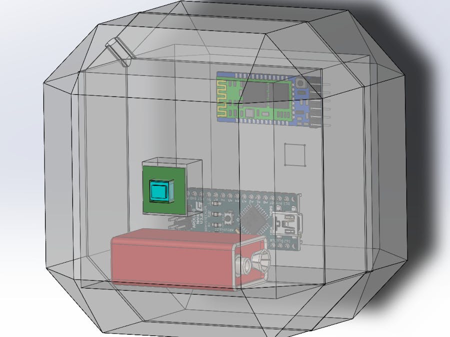
Step 2: 3D Printing
The 3d model for the Hexagon with the modules integrated is shown below-
Step 3: Assembly
After placing all the modules in the hexagon, the components were glued onto the enclosure to keep them fixed.
The second part of the module is assembled with a three-port outlet. The second module consists of an Arduino Nano, HC-05 module, a battery, and a relay. The 110v outlet was connected and configured to be switched by the Arduino nano. The assembled setup is shown below-
Step 4: Programming
Operation Flow Chart: Hexagon
1. Initialize
2. Light the RGB Led
3. Detect motion changes
4. If detected send light on the signal.
5. Wait for 30 sec.
6. Detect again.
7. If detected send light on signal again.
8. If not detected turn light off Signal.
Operation Flow Chart: Relay Controller
1. Initialize.
2. Check for signal (HC-05 module).
3. Turn light on if the light on the signal is received.
4. Turn light off if light off signal is received.
The Code
The following code is written and programmed to the Kemet-ProxiSense hexagon.
A debouncing filter was applied to get rid of the false detection. Such a technique can be easily used to filter out and making detection robust.
/*
Author: Arindam Biswas
Date: 02/28/2020
Contribution: Bruno Calou (Timer Arduino)
Description: This code is for the modular hexagon box which integrates the Kemet pyroelectric SS-430L-N Sensor.
The code is configured to filter out and trigger the on/off action which is sent over a Bluetooth link. For aesthetic purposes, the code also drives an RGB led.
*/

//Define RGB pins
int rGnd=9;
int rB=10;
int rG=11;
int rR=12;
int rDel=50;//ms

//Initialize RGB LED

void RGBInit()
{
pinMode(rGnd,OUTPUT);
pinMode(rR,OUTPUT);
pinMode(rB,OUTPUT);
pinMode(rG,OUTPUT);
digitalWrite(rGnd,LOW);
}

//RGB display function
void RGBPlay()
{
digitalWrite(rR,HIGH);
delay(rDel);
digitalWrite(rG,HIGH);
delay(rDel);
digitalWrite(rB,HIGH);
delay(rDel);
digitalWrite(rR,LOW);
delay(rDel);
digitalWrite(rG,LOW);
delay(rDel);
digitalWrite(rB,LOW);
delay(rDel);
}
#include "timer.h"
int SecC=0;
int Sens=0;
int led_pin = 13;  //Set our led pin
bool led_is_on = false;  //Holds if the led is on

//Timer object
Timer timer;

//Function for checking if any motion exists
//If exists then wait or send light turn off signal

void blinkLed() {
Sens=analogRead(A0);// reading Sensor
if(Sens>200)//
{
Serial.print(1);//Light on signal
}
else
{
SecC++;
if(SecC==30) { //Wait for 30 seconds
digitalWrite(led_pin, LOW);
SecC=0; //reset second timer
timer.stop(); //Stop the timer
Serial.print(0); //Send light off signal
}
}
//Change our led state
// led_is_on = !led_is_on;
}
void setup()
{
RGBInit(); // RGB initialization
pinMode(led_pin, OUTPUT);
Serial.begin(9600);

pinMode(A0,INPUT); // Input pin
//Set the interval in milliseconds we want the led to blink
timer.setInterval(1000);

//Set our callback function
timer.setCallback(blinkLed);

//Start the timer
timer.start();

timer.stop(); // initially stops the timer
}
void loop()
{
//Update the timer
timer.update();
RGBPlay();

Sens=analogRead(A0); //read motion data
if(Sens>200)
{
delay(100); //debouncing delay
Sens=analogRead(A0);
if(Sens>200) //checking if it was a false trigger
{
Serial.print(1); // confirm detection send light on signal
timer.start(); // start the wait timer
digitalWrite(led_pin, HIGH);
}
}
}
The relay setup code-
/*
* Author: Arindam Biswas
* Date: 03/01/2020
* Description: This section reads an HC-05 module for incoming trigger signal by serial link and drives the relay to switch appliance accordingly.
*/
int data = 9; // recieved data variable
void setup() {
// put your setup code here, to run once:
pinMode(2, OUTPUT); //relay pin 1 goes to coil one positive
pinMode(3, OUTPUT); //relay pin 2 goes to coil two positive
Serial.begin(9600);
pinMode(13, OUTPUT); // Led for indication
}
void loop() {
// put your main code here, to run repeatedly:
if (Serial.available() > 0) // checing if any signal is available to read in the buffer
{
data = Serial.read(); //read serial data
if (data == 49) // Data recieved led turn on
{
digitalWrite(2, HIGH);
digitalWrite(3, LOW);
digitalWrite(13, HIGH);
}
if (data == 48)// Data recieved led turn off
{
digitalWrite(3, HIGH);
digitalWrite(2, LOW);
digitalWrite(13, LOW);
}
}
}
Step 5: Testing
The video shows the basic working of the Kemet ProxiSense in which the motion trigger, Bluetooth link, and relay is tested-
Step 6: The Final Video
The final video is here :) -
Comment:
The Kemet Pyroelectric Proximity Sensor provides an excellent solution for motion detection over a traditional PIR sensor. It was really simple to use. Though false triggering was an issue with a decoupling capacitor and filtering (code- debouncing) it was easily dealt with. Overall, it's a cheap, efficient and effective module that can open anew window to motion detection.

Comments