


Hardware components | ||||||
 |
| × | 1 | |||
| × | 1 | ||||
 |
| × | 1 | |||
 |
| × | 3 | |||
 |
| × | 1 | |||
 |
| × | 1 | |||
 |
| × | 2 | |||
 |
| × | 1 | |||
| × | 1 | ||||
 |
| × | 1 | |||
 |
| × | 1 | |||
 |
| × | 1 | |||
 |
| × | 1 | |||
Software apps and online services | ||||||
 |
| |||||
| ||||||
Hand tools and fabrication machines | ||||||
 |
| |||||
| ||||||
It has been about a year since we have been learning Arduino. Since we do much with Arduino IDE, we were looking for a project that we could try all kinds of stuff. I mean crazy stuff. A project to get dirty, fail, fail more, and learn from those failures.
It was January 2015 when we had started to to lean about Arduino and Arduino IDE. Since then we started making small projects using Arduino mega 2560 and the Arduino IDE. The flexibility that we got is that we were able to load the program in the memory of the controller using mobile phones (Android). After lot of searching we got an application the was made for mobile phones through which we were able to program our controllers (Arduino) and that application name is "Arduinodroid".
Till March of 2015 we were learning about Arduino and doing small projects using Arduino we heard about something IOT that is Internet Of Things. This concept of IOT made us amaze and we eagerly started studying and doing research on IOT. This curiousness brought us to do this amazing project "Home Automation using IOT".
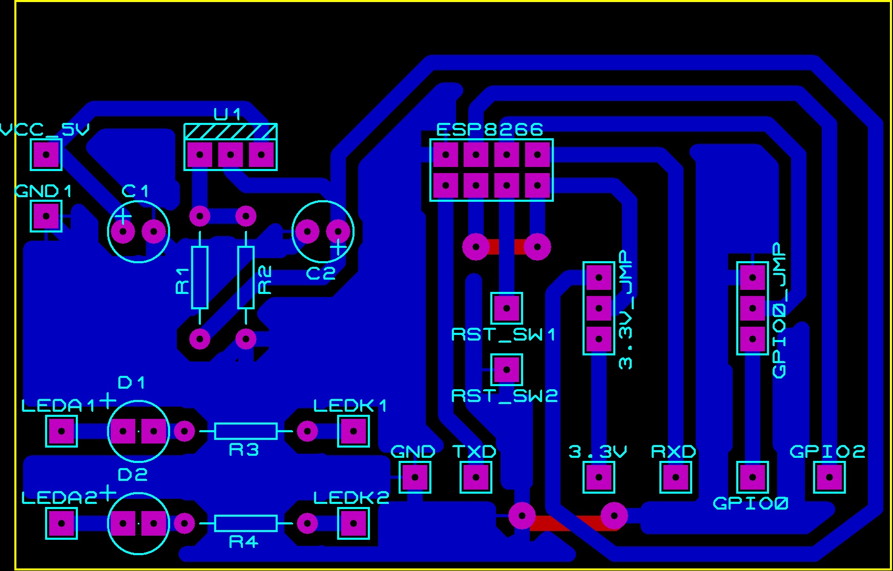
STEP 1: Building PCBMake the design of PCB as the image prescribed below and take a printout of it on the photo paper using Inkjet printer and paste in on the plain copper clad(PCB before the tracks made) using an iron. When you see the track masked over the clad put the clad into FeCl3 solution(PCB itching) for about 15 min.
After the PCB itching is completed we will see the tracks only of copper. Now drill the holes where ever it is required and the PCB is ready for the project.
OR
Download the GERBER file available in the attachments and give it to the PCB itching vendor and the PCB it is ready for the project.
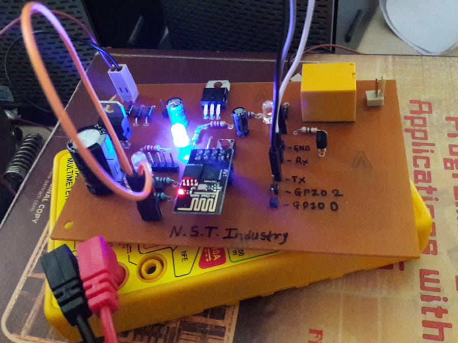
STEP 2: Placing components.All the components described should be available to mount on the PCB. Place the components one by one on the PCB and solder the components neatly. After completion of mounting the components check the voltage supplied to the modules Vcc point or at the output of the LM315, it should not exceed 3.7V i.e. the max voltage the module can sustain. Now the dev board is ready to upload the code and to test it.
STEP 3: Adding ESP board to IDE.Open the arduino IDE which should display the default screen of code with setup and loop function. Now to add the ESP board to the IDE click File->Preferences and we see a tab opened, find out the Additional boards manager urls. Paste this URL in that box http://arduino.esp8266.com/stable/package_esp8266com_index.json and close the the Preferences tab.
Now click Tools->Board->Board manager... after clicking, the board manager tab is opened and in the search box search for "ESP" and install the "esp8266 by ESP8266 Community".
Thats it, ESP board is added to the IDE.
STEP 4: Making the website.To create a free website there are many vendor who offer we website hosting. For convenience we shall use the 000webhost.com which also give free web hosting. Open a new account by signing up or if you an account then login. After login choose a website name and open the file manager and goto "public_html" where our website's HTML code need to be placed.
Now download/copy both HTML and CSS file from the attachments and upload to it to the "public_html" folder in the file manager. Now try to open the website with the website name we choose, it should open the website and should display 2 Green button and 2 Red button.
That's how we built our website and is ready to use in the project.
STEP 5: Uploading the code.The most important thing to upload the code to the module is the FTDI. Connect the FTDI to the computer and also install the required drivers respective to FTDI. Now to find the COM port of the FTDI go to the device manager of the computer and in the PORTS the COM port is available that is assigned to the the FTDI. If we get an exclamation(!) mark with the COM port name then update the drivers of FDTI.
Connection from FTDI to Dev board.
FTDI Dev board
3.3V ----> Vcc
GND ----> GND
Tx ----> Rx
Rx ----> Tx
Place the module in the female headers and make sure the the red led is blinking and also the blue led. Which indicate the connection of the board are correct and no error is present.
Download or Copy the arduino code which can be found in the attachments and paste it in the Arduino IDE. Do some editing in the code, change the WiFi SSID with your WiFi SSID and also password of it. Now change the Website URL in the code with your website address. Select the "Generic ESP8266 module" from Tools->Board->Board manager... for compilation and also select the FTDI's Com port from Tools->Board->Port. Do not change any other setting in the Tools drop down list.
Compile the code and upload to the module. If any error occurs then do comment in the comment box below.
Step 6: Testing.Now connect the GPIO0 pin to first LED+ and it's LED- to GND and GPIO2 pin to second LED+ and it's LED- to GND. Press the reset button and check the Serial monitor in the computer for the messages sent by the module which displays the status of the communication of module with the website server.
Open the website and click any button and the result shall be seen on the LED status(ON or OFF).
If the LED blink as per the user input on the website then the project is successfully tested.
STEP 7: Implementation.Connect the GPIO0 and GPIO2 pin to the Relay board which can drives the AC devices. So when we change the status on the website then our home appliance AC device's status is also changed.
Congratulations! You learned to control your home appliances over the Internet using a small device ESP8266.
Isn't it an amazing project using IOT? Cool right.
Thank for implementing the project and don't forget to like, comment and follow.


Comments