


Hardware components | ||||||
 |
| × | 1 | |||
 |
| × | 1 | |||
 |
| × | 1 | |||
 |
| × | 400 | |||
 |
| × | 200 | |||
 |
| × | 1 | |||
| × | 1 | ||||
| × | 1 | ||||
|
| × | 1 | |||
| × | 1 | ||||
Software apps and online services | ||||||
 |
| |||||
 |
| |||||
| ||||||
| ||||||
| ||||||
 |
| |||||
Hand tools and fabrication machines | ||||||
 |
| |||||
 |
| |||||
 |
| |||||
 |
| |||||
In the dense forests and mountainous regions of Kerala, especially areas like Nelliampathy, wild elephants frequently traverse routes that have been part of their migratory patterns for centuries. These pathways, known locally as “Aanathaara” (elephant corridors), are deeply embedded in the landscape and ecology. However, with rapid human expansion — including roads, farmlands, and settlements — these natural trails now intersect with human activity, often with devastating consequences.
While locals may instinctively understand where and when to be cautious, most visitors, tourists, and even daily commuters remain unaware of the risks.In early 2025, a tragic incident occurred in Nelliampathy, Kerala. A German tourist, unfamiliar with the terrain and unaware of a wild elephant blocking the road, ventured forward despite the locals’ warnings. Tragically, he encountered the elephant and lost his life. Traditional static signage, such as painted boards warning of elephants, often fades into the background and fails to provide real-time, actionable alerts. The result? Dangerous — and sometimes fatal — encounters that could have been avoided with better awareness.
That's where EleTect 1.5 comes in — combining TinyML, LoRa, solar power, and interactive signage to proactively warn and deter.
🛠️ What It DoesEleTect 1.5 is an advanced extension of the award winning EleTect 1.0 system. It introduces an interactive digital signage system that provides real-time warnings to riders and drivers when elephants are present ahead on forest roads.
🐘 EleTect Node (Detection Unit)
- Detects elephants using a TinyML-powered system which can identify an elephant using vision and sound.
- Uses LoRa to send elephant presence status to the signage node.
- Triggers a deterrent mechanism (e.g., honeybee sound)
🚦 Signage Node (Warning System)
- Placed 500m before known elephant crossings.
- Displays a bright, red, flashing elephant warning.
- All powered entirely by solar energy.
- Elephant detected ➡️ EleTect Node triggers LoRa alert to Sign Board.
- Signboard flashes elephant warning if vehicles are approaching.
EleTect Node waits 10 minutes → plays deterrent bee sound.
- After elephants leave, detection stops → Signboard resets.
Eletectis a technology-driven system designed to detect elephants early, deter them harmlessly, and alert nearby communities. Its goal is to protect lives, foster coexistence, and contribute to wildlife conservation.
Despite their size and power, elephants have a surprising vulnerability: they are instinctively afraid of bee buzzing sounds. By carefully and harmlessly using this natural deterrent, Eletect can safely redirect elephants away from human settlements without harming them. This peaceful strategy respects both humans and elephants.
⚙️ How it WorksAt the forest boundaries, multiple TinyML-powered nodes are deployed. Each node can:
- Detect elephants using a vision-based TinyML model on the Seeed Studio Grove Vision AI V2 module.
- Analyze sound using a Seeed Studio XIAO ESP32S3 Sense, running a TinyML audio model to detect elephant vocalizations.
- Trigger deterrents by playing honeybee buzzing sounds through an onboard speaker.
- Communicate via LoRa/LoRaWAN with a central master node to ensure real-time updates even in remote areas.
The system is completely solar-powered, making it sustainable and ideal for deployment in remote forest region
🌿 Field Survey, Official Approval & Real-World TrialsTo ensure EleTect was not just a lab prototype but a real-world conservation tool, our team carried out an extensive ground survey and obtained official permission for field testing from the Divisional Forest Officer (DFO) of Kothamangalam, Mr. Varun Dalia, IFS, and Forest Range Officer, Mr. Jaleel.
🧭 On-Ground Survey & Study AreaThe field research took place in Kothamangalam and Kottapady, Kerala — regions at the edge of the Western Ghats that experience frequent elephant incursions into farmlands and villages.
We conducted household-level surveys to assess the scale and nature of human–elephant conflict (HEC) in these areas.From 100 surveyed households, 85 reported direct encounters with elephants, while:
- 66% suffered crop destruction, and
- 38.4% experienced human injury or fatalities related to elephant incidents.
This data emphasized the urgent need for early warning and deterrent systems like EleTect.
🏛️ Collaboration & Forest Department ApprovalAfter the survey phase, we formally presented EleTect to the DFO Office, Kothamangalam, and Forest Range Office to discuss its technical operation, safety, and ecological compatibility.
Following evaluation, the Forest Department granted permission to conduct live field trials in designated forest-border regions.
This collaboration provided both ethical validation and administrative support, ensuring that EleTect aligns with wildlife protection policies and sustainable forest management goals.
🌍 Field Testing & ObservationsWith official clearance, EleTect nodes were deployed across select hotspots along the forest–village interface in Kothamangalam.Each unit combined vision + acoustic TinyML detection and LoRa communication to identify elephants and other sounds in real time.
Local communities and forest officers both reported positive feedback, reinforcing EleTect’s value as a safe and practical conservation technology.
ArchitectureSignages will be placed like below.
Component
XIAO ESP32S3
Grove LoRa-E5 Module
Solar Charging Modules
Custom battery pack
Custom LED panel
Enclosure Using Acrylic sheet
🛠️ Step 1: Build the Custom Signage EnclosureIn this step, we’ll create a weatherproof and visually impactful enclosure that houses the electronics for the elephant warning signage system. The enclosure is made from 5mm clear acrylic sheets, designed in Fusion 360, and laser cut for precision.
🧰 Materials Needed- 5mm thick clear acrylic sheet
- Access to a laser cutter
- Acrylic glue (e.g., Weld-On 3 or Fevikwik)
- Vinyl cutter and precision knife
- Reflective vinyl sticker sheet (yellow and red)
- Matte black vinyl sheet
- Clamps or tape for alignment
- Fusion 360 or similar CAD software
- Cooling film
Create a Design in Fusion360 for the enclosure.
Sketch the front panel dimensions based on your component layout (camera, LEDs, LoRa antenna, etc.).Ensure the box has enough depth to house the electronics.
Export each face of the enclosure as a DXF file for laser cutting.
- Upload the DXF files to your laser cutter’s software.
- Set your laser cutter to the appropriate power/speed settings for 5mm acrylic.
- Carefully cut each panel and label them as you go to avoid confusion during assembly.Peel off any protective film after cutting.
👉 Safety first! Wear proper eye protection and operate the cutter in a ventilated area.
Lay out all the cut pieces on a clean surface.
Begin with the base and edges.Apply acrylic glue along the joining edges and press pieces together.Use clamps or masking tape to hold parts in place until dry.
Continue assembling all sides until the box is complete.
Let the entire assembly cure for several hours to ensure strong bonding.
👉 Tip: Double-check the alignment before applying glue — acrylic bonds instantly!Grind and smoothen the Irregular edges using a grinding tool.
✨ Step 1.4: Apply the Reflective GraphicsDesign an elephant silhouette and the text “ELEPHANTS AHEAD” using vector software (e.g., Adobe Illustrator or Inkscape).
Cut the design using a vinyl cutter from reflective vinyl sheet.
Clean the front acrylic panel with a microfiber cloth.Carefully transfer the reflective vinyl design onto the panel using transfer tape.
Cover the remaining back and side edges with matte black vinyl to block internal components and focus attention on the warning.
👉 Result: A bold, reflective front that is highly visible when headlights or onboard LEDs shine on it.
💡 Step 2: Building the Custom LED PanelIn this step, we’ll design and assemble a high-visibility LED panel in the shape of an elephant, mounted inside our previously built acrylic enclosure. This panel serves as a visual alert, visible from a distance even in low-light conditions.
🧰 Materials Required- 4x generic dotted PCBs (perforated board)
- 400x 5mm Red Clear LEDs
- 200x 68Ω resistors
- 22 AWG hookup wire
- Soldering iron + solder wire
- Black matte spray paint (optional, for aesthetics)
- 1x N-channel MOSFET (e.g., IRLZ44N)
- 1x 220Ω resistor (for MOSFET gate)
- 1x Custom 3S3P LiPo battery pack (11.1V nominal)
- Heat shrink, glue, basic tools
Take your four dotted PCBs paint them with matte black paint — this step is optional but gives a professional look and improves contrast against the red LEDs.
Let them dry completely.
👉 Tip: Paste a sheet or paper on the back of the pcb before painting so that the paint won't get into the backside✂️ Step 2.2: Join the PCBs to Form a Large Panel
Measure and cut the boards to your desired dimensions.
Carefully align and glue the four PCBs together to create a larger panel.
Make sure all the solder pads align properly and the board is flat.
🐘 Step 2.3: Trace and Plan the LED LayoutPlace the vinyl elephant signage or sticker over the panel as a reference.Using a white marker or chalk, roughly trace the outline of the elephant and the text “ELEPHANTS AHEAD”.
Plan the LED positions inside this trace to match the shape as closely as possible
👉 Tip: Leave a bit of spacing between each LED to avoid overcrowding.
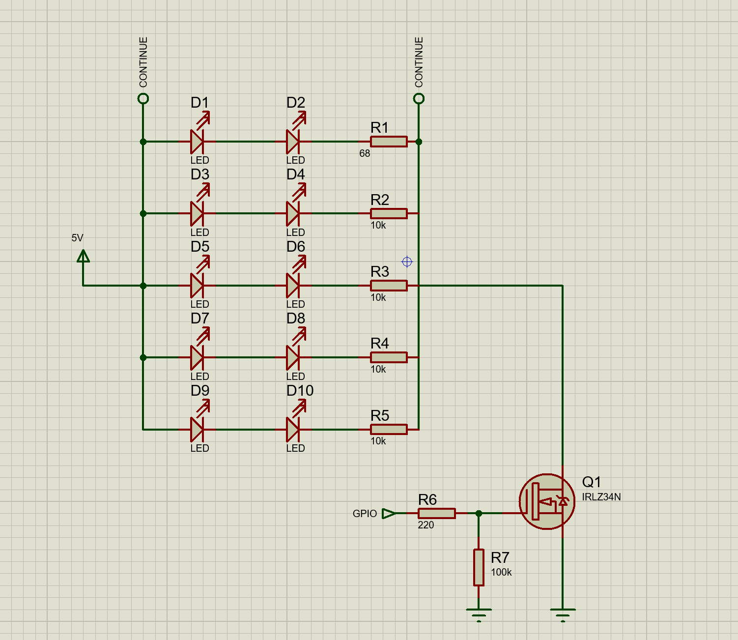
🔗 Step 2.4: LED Chain DesignWe’ll use a simple and efficient wiring scheme:
2 LEDs in series + 1 resistor (68Ω) = 1 chain
Multiple such chains are wired in parallel across the panel
Why this config?With a 3S (11.1V) LiPo battery, 2 red LEDs (approx. 2V each) + 68Ω resistor draws safe current and provides balanced brightness.
🧪 Step 2.5: Prototype and Test the LED CircuitFirst, build one LED chain on a breadboard.
Power it using a bench power supply.
Confirm brightness and measure current draw.Once satisfied, continue soldering the full design onto the board.
🔩 Step 2.6: Solder All LED ChainsStart from the top of the board, following your traced outline.
Insert 2 LEDs in series and connect the 68Ω resistor to complete the chain.Continue placing and soldering LED chains across the board, following your elephant outline and text.
Use thin wires to connect common positive and negative rails at the back.
After soldering, check for shorts and test small sections individually.
⚡ Step 2.7: Power and Drive CircuitConnect all the negative lines from each LED chain to a MOSFET drain.Connect the MOSFET source to ground.Use a 220Ω resistor on the MOSFET gate and connect it to your microcontroller’s digital output (for PWM or ON/OFF control).The positive rail of all LED chains goes directly to the power supply.
Check heat levels and ensure no resistors or LEDs are overheating.
✅ Final TestingSecurely mount the pack inside the enclosure and wire it to the LED panel via a toggle switch or microcontroller control..Turn on the system and ensure all LEDs light up in the correct pattern.
But unfortunately, it didn’t quite meet my expectations. During the first test, I wasn’t fully satisfied, as it didn’t look as refined or close to the vision I had in mind.
But then I had a small idea — if I could diffuse the LED light, it might look much cleaner and more aesthetically pleasing. To quickly test this, I placed a simple A4 sheet between the front acrylic panel and the LED panel.
After diffusing it with an A4 sheet, the display looked even better—cleaner and clearer. There were some dead LEDs, so I replaced them and it worked perfect.
Initially, my idea was to keep the elephant silhouette completely black when the sign was inactive and then illuminate it in red once activated. To match this concept, I painted the PCB black so that the LEDs would remain invisible until turned on. However, when I tried adding a simple A4 sheet as a diffuser, it disrupted the clean aesthetic I was aiming for, as the sheet made the panel look less appealing.
To tackle this, I thought of using smoked acrylic. This material would give the panel a sleek black look when off, while still allowing the red LEDs to shine through when active. Pairing it with a thin frosted acrylic sheet underneath would help diffuse the light evenly, achieving both functionality and the desired aesthetics.
The challenge, however, was that smoked acrylic was not easily available at the time, and even if sourced, it would add to the cost and overall weight of the system. To find a more practical alternative, I came up with the idea of applying car window cooling film to the back of the front panel to replicate the smoked effect. For light diffusion, I could then use a lightweight and low-cost option like a thin plastic sheet or even butter paper. This way, I could preserve both the aesthetics and the functionality without compromising on budget or weight. Firstly apply the cooling film on the back of the front acrylic panel.
Then use a thin plastic sheet or butter paper to diffuse the light on top of that.
So to test it I quickly made a setup and tested it.
Finally, after several trials, I was able to achieve exactly the result I had envisioned: a signage system that remains sleek and minimal when inactive, but transforms into a striking, attention-grabbing warning when activated.
Now that we have our physical enclosure and the custom LED warning panel ready, it's time to connect the system to the EleTect detection node using LoRa communication.
📡 Communication Architecture:1.EleTect Node (Forest-side)
Detects elephant presence using:
- Grove Vision AI V2 → vision-based elephant detection.
- XIAO ESP32S3 Sense → sound-based detection.
- On detection → Sends
ELEPHANT_DETECTEDmessage via LoRa to the Signboard Node. - Sends
ELEPHANT_LEFTwhen elephants leave → resets the system.
2.Signboard Node (Roadside)
- Listens for elephant alerts from EleTect Node.
- On detection → flashes warning LED (with elephant symbol) continuously until elephant leaves.
Outcome
- 🚦 Elephant but no vehicles → Only flashing signboard (no sound, less disturbance).
- 🚦 Elephant + vehicles present → Signboard flashes + EleTect triggers bee sound after 10 minutes.
- ✅ Once elephant leaves → Signboard turns off, deterrent stops, system resets.
- XIAO ESP32S3 – For LoRa and LED control
- LoRa-E5 Grove Module – For receiving data from EleTect node3S3P Li-ion Pack – Custom power solution for high LED current drawMOSFET (e.g., IRF540N or similar) – To drive the LED panel
- 220Ω Resistor – Gate resistor for the MOSFET
- Jumper Wires
Here's a basic sketch to control the LED flashing when elephant presence data is received from the EleTect node.
🧾 Code for the Signboard Node (Receiver):/*
Signage node for XIAO ESP32S3
- Listens for "elephant" messages from EleTect node over Meshtastic
- When elephant reported: blink a red signage LED (MOSFET-driven) for 40s after last report
- Uses Grove Vision AI V2 to detect "vehicle" on road and reports vehicle events to EleTect node
via Meshtastic ]
Pin & behavior configuration near top.
*/
#include <Arduino.h>
#include <Seeed_Arduino_SSCMA.h> // Grove Vision AI V2
// ----------------- CONFIGURATION -----------------
// Meshtastic serial (to Wio SX1262 Serial Module)
const int MESHTASTIC_RX_PIN = 16; // XIAO RX (connect to Wio TX)
const int MESHTASTIC_TX_PIN = 17; // XIAO TX (connect to Wio RX)
const unsigned long MESHTASTIC_BAUD = 38400UL; // must match Serial Module baud
// Grove Vision AI V2 UART - use a second serial port
// On XIAO ESP32S3 we will use atSerial (HardwareSerial(0)) for Grove Vision if desired.
// Seeed library uses a HardwareSerial pointer when calling begin(). Keep as is.
#ifdef ESP32
#include <HardwareSerial.h>
HardwareSerial atSerial(0); // Grove Vision AI UART (example)
#else
#define atSerial Serial1
#endif
Seeed_Arduino_SSCMA AI; // Grove Vision AI object
// LED signage output (MOSFET gate)
const int SIGN_LED_PIN = 25; // change to the MOSFET gate pin you connected
// Blink pattern configuration
const unsigned long SIGNAGE_TIMEOUT_MS = 40UL * 1000UL; // 40 seconds after last elephant message
const unsigned long BLINK_ON_MS = 300; // LED on duration in blink cycle
const unsigned long BLINK_OFF_MS = 300; // LED off duration in blink cycle
// Vision detection threshold and interval
const int VISION_SCORE_THRESHOLD = 80; // Grove Vision AI score threshold (0..100)
const unsigned long VISION_POLL_MS = 800; // how often to invoke vision model
// Vehicle reporting cooldown so we don't spam the network
const unsigned long VEHICLE_SEND_COOLDOWN_MS = 10000UL; // 10s between vehicle reports
// -------------------------------------------------
// State variables for signage
volatile unsigned long lastElephantMs = 0; // last time an elephant message was received
bool signageActive = false;
// Blink state machine
bool blinkStateOn = false;
unsigned long blinkStateChangeAt = 0;
// Vision timing
unsigned long lastVisionPollAt = 0;
unsigned long lastVehicleSentAt = 0;
// Serial buffer for incoming meshtastic lines
String incomingLine = "";
// Helper: send JSON line to meshtastic serial (TEXTMSG mode)
void sendMeshtastic(const String &payload) {
// send as a simple line; Meshtastic Serial Module will handle sending as TEXTMSG
Serial.print("-> meshtastic: ");
Serial.println(payload);
Serial2.println(payload);
}
// Parse incoming serial line(s) from Serial2 for elephant messages
void processIncomingLine(const String &line) {
String lower = line;
lower.toLowerCase();
if (lower.indexOf("elephant") >= 0) {
// Elephant spotted by remote node
lastElephantMs = millis();
signageActive = true;
// Reset blink state so LED turns on immediately
blinkStateOn = true;
blinkStateChangeAt = millis();
digitalWrite(SIGN_LED_PIN, HIGH);
Serial.println("Elephant message received -> signage activated (40s timeout).");
} else {
// Not elephant; optionally inspect other incoming messages if needed
Serial.print("Incoming (ignored): ");
Serial.println(line);
}
}
// Read any available bytes from Serial2 and accumulate lines
void pollMeshtasticSerial() {
while (Serial2.available() > 0) {
char c = (char)Serial2.read();
if (c == '\r') continue;
if (c == '\n') {
String line = incomingLine;
line.trim();
incomingLine = "";
if (line.length() > 0) {
processIncomingLine(line);
}
} else {
incomingLine += c;
// Keep buffer bounded
if (incomingLine.length() > 1024) {
incomingLine = incomingLine.substring(incomingLine.length() - 512);
}
}
}
}
// Non-blocking blink update; keep LED toggling while signageActive
void updateBlinkState() {
if (!signageActive) {
// ensure LED off
if (blinkStateOn) {
blinkStateOn = false;
digitalWrite(SIGN_LED_PIN, LOW);
}
return;
}
unsigned long now = millis();
if (blinkStateOn) {
if (now - blinkStateChangeAt >= BLINK_ON_MS) {
blinkStateOn = false;
blinkStateChangeAt = now;
digitalWrite(SIGN_LED_PIN, LOW);
}
} else {
if (now - blinkStateChangeAt >= BLINK_OFF_MS) {
blinkStateOn = true;
blinkStateChangeAt = now;
digitalWrite(SIGN_LED_PIN, HIGH);
}
}
// Deactivate signage if timeout elapsed since last elephant message
if (now - lastElephantMs >= SIGNAGE_TIMEOUT_MS) {
signageActive = false;
blinkStateOn = false;
digitalWrite(SIGN_LED_PIN, LOW);
Serial.println("Signage timeout expired -> signage deactivated.");
}
}
// Vision: poll Grove Vision AI V2 and send vehicle messages via meshtastic if vehicles found
void pollVisionAndReport() {
// The SSCMA library uses AI.invoke(1,false,false) returning 0 on success in earlier examples.
// We will follow that pattern; adjust if your library differs.
if (!AI.invoke(1, false, false)) { // single invoke, no filter, no image
for (int i = 0; i < AI.boxes().size(); i++) {
int score = AI.boxes()[i].score;
if (score > VISION_SCORE_THRESHOLD) {
String label = AI.boxes()[i].label;
String lower = label;
lower.toLowerCase();
if (lower.indexOf("vehicle") >= 0 || lower.indexOf("car") >= 0 || lower.indexOf("truck") >= 0 || lower.indexOf("bus") >= 0) {
unsigned long now = millis();
if (now - lastVehicleSentAt >= VEHICLE_SEND_COOLDOWN_MS) {
lastVehicleSentAt = now;
// Create a compact JSON payload; adjust fields as your EleTect node expects
String payload = String("{\"event\":\"vehicle\",\"score\":") + String(score) + String(",\"t\":") + String(now) + String("}");
sendMeshtastic(payload);
Serial.printf("Vehicle detected (score %d) -> sent vehicle message\n", score);
} else {
Serial.println("Vehicle detected but on cooldown (skip sending).");
}
}
}
}
} else {
// AI.invoke returned non-zero according to earlier API — nothing or error
// You can print debug here if needed
// Serial.println("Vision: no boxes or invoke returned non-zero");
}
}
void setup() {
Serial.begin(115200);
while (!Serial);
Serial.println();
Serial.println("Signage node booting...");
// LED pin
pinMode(SIGN_LED_PIN, OUTPUT);
digitalWrite(SIGN_LED_PIN, LOW);
// init meshtastic serial on Serial2 (hardware serial) with provided pins
// Use Serial2 for XIAO ESP32S3 (change to Serial1 if you wired differently)
Serial2.begin(MESHTASTIC_BAUD, SERIAL_8N1, MESHTASTIC_RX_PIN, MESHTASTIC_TX_PIN);
delay(50);
Serial.println("Meshtastic UART (Serial2) initialized.");
// init vision ai - wire to hardware serial or the same Serial? Use atSerial (HardwareSerial(0)) as in examples
#ifdef ESP32
atSerial.begin(115200);
AI.begin(&atSerial); // Grove Vision AI using hardware serial 0
#else
atSerial.begin(115200);
AI.begin(&atSerial);
#endif
Serial.println("Grove Vision AI v2 UART initialized.");
lastElephantMs = 0;
signageActive = false;
blinkStateOn = false;
blinkStateChangeAt = millis();
lastVisionPollAt = 0;
lastVehicleSentAt = 0;
Serial.println("Setup complete.");
}
// Main loop: poll meshtastic input, update blink state, and periodically poll vision
void loop() {
// 1) Handle incoming meshtastic messages from other nodes
pollMeshtasticSerial();
// 2) Update blink state machine (non-blocking)
updateBlinkState();
// 3) Poll vision at intervals and optionally report vehicles
if (millis() - lastVisionPollAt >= VISION_POLL_MS) {
lastVisionPollAt = millis();
pollVisionAndReport();
}
// small yield
delay(10);
}The entire signboard is powered by a custom 3S3P battery pack made using Li-ion cells (11.1V ~ 12.6V).And downed using a buck converter to 5V.
The MOSFET allows the microcontroller to switch the high current LED panel without overloading the XIAO.
🧩 Step 5: 3D Printing and Mounting the LED Panel to a Custom StandStand Construction from Scrap MetalTo reduce costs and promote sustainability, the stand for the EleTect warning signage and solar panel was made entirely from scrap metal. Despite being built from repurposed material, it is sturdy, weather-resistant, and highly visible.
Materials Used- 1-inch square metal pipe (scrap, reused)
- Welding machine (for joints)
- Cutting tool (angle grinder)
- Anti-rust paint (to protect against corrosion in forest conditions)
- Mounting bolts & brackets (for signage + solar panel)
- Height: ~8 feet (tall enough for clear visibility to drivers).
- Pole: Single vertical square pipe serves as the main post.
- Base: Welded flat support with angled bracing, bolted into the ground for stability.
Top Section:
- Solar panel mounted with a small angled bracket for optimal sunlight.
- Warning signage (“Elephants Ahead”) firmly attached just below the panel.
- Cutting the Scrap Pipe:The scrap pipe was cut into one 8 ft piece (main vertical) and smaller pieces for the base support.
- Building the Base:A flat base with short stabilizers was welded to the bottom so it could be anchored securely into the ground with bolts.
Mounting the Sign & Solar Panel:
- A horizontal bracket at the top holds the solar panel at an angle.
- The triangular signage board is bolted slightly below the solar panel.
Painting & Finishing:The entire stand was coated with anti-rust paint, ensuring long durability outdoors.
BenefitsUltra Low Cost: Made from waste scrap material.
Eco-Friendly: Reuses metal that would otherwise be discarded.
Durable: Strong enough to withstand wind, rain, and wildlife contact.
Scalable: Simple design can be replicated in bulk for multiple forest corridors.
Designing the Mount
To ensure stability and long-term deployment in outdoor environments, we designed a custom 3D printed mount that securely holds the LED signboard and aligns it on the custom metal pipe-based stand.
🛠️ Materials Used:- PLA filament (Black)
- 3D printerM4 bolts and nutsScrews (for enclosure-mounting)steel pipe (for pole mounting)
CAD Modeling:
Using Fusion 360 design a mounting bracket that matches the dimensions of the acrylic signboard enclosure
Printing:
Assembly:
Once printed, the enclosure was carefully slotted into the mount
Secure with M4 bolts on either side to lock it in place.The mount was then clamped or screwed onto a metal/PVC pole, completing the physical installation..
🌍 Sustainability and Edge Deployment- No internet required: Uses LoRa for remote communication
- Fully solar-powered, ideal for deployment in forest areas
- Deterrent only activates when necessary, conserving energy and minimizing disturbance to wildlife
One of the most impactful upgrades we are planning for EleTect is the integration of Google Maps into the system. Currently, EleTect is capable of detecting elephant movement and triggering local deterrents or alerts. However, by incorporating Google Maps, we aim to create a real-time, centralized monitoring system that will drastically improve response times and ensure safer coexistence between humans and elephants.
🔹 How It Will Work:
- Live Location Mapping – Each EleTect unit deployed in the field will send detection data (timestamp, location coordinates, and event details) to a central cloud server.
- Google Maps Visualization – The data will be displayed on Google Maps, showing the exact position of elephant sightings or conflicts in real-time.
- Risk Zone Alerts – Areas with frequent detections will be marked as “High Risk” zones, allowing authorities and locals to take precautionary measures.
- Community Access – Farmers, drivers, and forest officials will be able to access a live web/app dashboard powered by Google Maps, ensuring they are instantly informed of nearby elephant movement. Historical Data & Prediction – By overlaying historical data on Google Maps, the system can predict elephant routes and hotspots, helping in long-term conflict mitigation planning.
🔹 Benefits:
- Prevent Road Accidents – Drivers will receive live alerts on elephant crossings ahead, reducing the risk of collisions (like the unfortunate German tourist incident).
- Safer Agriculture – Farmers can check real-time elephant movement before stepping into their fields at night.
- Better Resource Deployment – Forest officials can allocate patrols and deterrents more effectively.
- Community Awareness – Local communities gain accessible, visual information, fostering safer human-elephant coexistence.
While designed for mitigating human-elephant conflict, the system can also be adapted for other regions and animals, such as kangaroos, deer, or bison, with only minimal modifications required. The overall goal remains the same: to reduce accidents, save human lives, and protect wildlife.
This integration will make EleTect not just a detection and deterrent system, but a smart, location-aware safety network that can save countless lives – both human and elephant.
🌱 Let’s Save Lives — Humans and Elephants AlikeWith EleTect 1.5, we bridge the communication gap between the wild and the road. Let’s make our forests safer — not by blocking wildlife, but by understanding and respecting their paths.
📎 Resources


_t9PF3orMPd.png?auto=compress%2Cformat&w=40&h=40&fit=fillmax&bg=fff&dpr=2)


Comments