

_QbCXr8JMJV.jpg?auto=compress%2Cformat&w=900&h=675&fit=min)
Hardware components | ||||||
| × | 1 | ||||
 |
| × | 1 | |||
| × | 1 | ||||
_ztBMuBhMHo.jpg?auto=compress%2Cformat&w=48&h=48&fit=fill&bg=ffffff) |
| × | 1 | |||
 |
| × | 1 | |||
Software apps and online services | ||||||
 |
| |||||
| ||||||
 |
| |||||
Hand tools and fabrication machines | ||||||
| ||||||
| ||||||
Airquality Monitoring is extremely important as often gases such as carbon-monoxide or volatile organic compounds (VOCs) can spread in a room leading to hazardous conditions to our health .The motivation for this project comes from helping my friend with the bodywork of his car and this process involves a lot of welding and handling chemicals that have toxic VOCs. The garage has no heating system hence during winter when the garage doors and windows are closed due to extreme cold there is very little air circulation.
Winter Is Coming!!
We will use a propane heater to warm-up the garage before doing repairs during winters which cause emission of Carbon Monoxide (CO) and will make use of chemicals containing volatile organic compounds (VOCs). Therefore having a wireless system to monitor the air quality, temperature and humidity will prove very useful as we will know the condition of the air before we go out to the garage. For example if we didn't shut off the propane gas supply properly or if the level of CO is too high we will see an anomaly in the PPM graph for VOCs and Carbon Monoxide.
The device equipped with the Helium kits, BME 680 and the MiCS 5524 is able to monitor :
- Temperature
- Humidity
- CO PPM
The sensor is designed to detect numerous gases and in the context of my application carbon-monoxide is the most important.
Adafruit BME 680:
The BME 680 uses and I2C interface to report temperature and humidity.
MiCS5524 Calibration:
From the datasheet of the MiCS5524 we can see its response to different gases. The MiCS5524 works by comparing its current internal resistance (RS) with a previously calibrated resistance (RO) in ideal conditions. This sensor operates over a wide range of temperatures which makes it ideal for the garage in winter and summer.
RS - current analog output from sensor
RO- previously set calibrated resistance in ideal conditions.
However defining a fixed RO value as the reference is not a good idea since from the datasheet show that RO is heavily affected by the humidity and temperature.
Hence turning on the device prior to will for it to run an accurate calibration function where it measures the current RS and sets it as the reference resistance RO. If it sees a RO resistance that is out of spec it will light its diagnostic LED brick red to show that calibration was not sucessful.
The graph below shows the relationship between PPM and RS/RO. This graph was plotted in excel by using the graph in the datasheet.
Implementing the above graph's equation in algorithm would be hard and inefficient. Hence natural logarithm was used to linearize the graph. The following graph and equation was obtained.
This linear graph gives a more efficient and reliable algorithm. This is repeated for the other gases to be measured. In my case since i have ethanol more readily available than carbon monoxide, i included that in my calculations.
CO Threshold:
In my code the thresholds are as follows for Carbon Monoxide:
- 0 - 5 - Diagnostic LED Green
- 5 - 7 - Diagnostic LED blinks Yellow
- 7 - 10 - Diagnostic LED blinks Red
The data is represented on Google Data studio as shown below:
Here is a brief step by step process just to set up project to get JSON key .
Note: Details about data studio or Big Query not included please see online guide as they are very detailed.
Step 1:
Create google account and sign in for Google IoT core.
Step 2:
Select dropdown on the top left and click on create new project.
Step 3:
Select a project name and location is optional.
Step 4:
Click on the top left icon to view all tools and features available.
Step 5:
Select IoT Core from the menu and Enable the API .
Step 6:
Create device registry and remember the registry ID as you would need to put it in the Helium dashboard.
Step 7:
Create a pub/sub topic and remember that name as you will need it in BigQuery .
Step 8:
Select Service account and generate a JSON key to be pasted in the dashboard.
This key must be used when creating a channel from the Helium dashboard.
3D Case DesignThe case was designed in freeCAD and simple3D. The idea was to have fan for air intake during calibration and checking if not part of the air is saturated with chemicals. Hence the bottom case was designed to incorporate a fan but also have vents to let the air go towards the sensors and out of the case. The following designs were made:
The 3D case was printed and came out as expected.
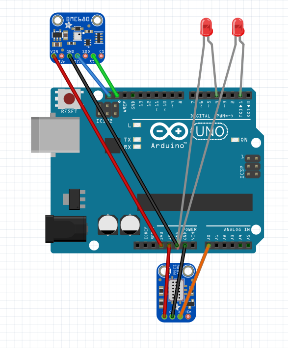
The schematic shown below is a high level drawing and does not include fan. The main components which are the LEDs and Sensors are shown.

Comments