

Hardware components | ||||||
 |
| × | 1 | |||
 |
| × | 1 | |||
| × | 1 | ||||
| × | 2 | ||||
 |
| × | 1 | |||
Software apps and online services | ||||||
 |
| |||||
Hand tools and fabrication machines | ||||||
 |
| |||||
If you have ever played snooker, you must have an idea of the problem of counting your score; you are in doubt most of the time about it. Surely, you can get a scoreboard which looks like this:
So whenever I would play snooker, I thought there has to be a better solution, and when I saw Infineon's 3D Magnetic knob, I got the idea of building a digital scoreboard.
This is a demonstration video of the final product:
And another one for 4 players:
These are the parts needed to build the digital scoreboard:
The MAX32620FTHR is used because of it's extensive features, allowing you to modify the digital scoreboard in any way you want.
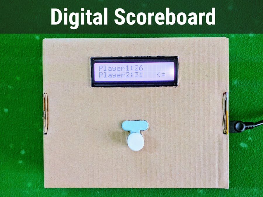
Data from the magnetic sensor on the XMC2Go kit is transmitted in a formatted string through UART to the MAX32620FTHR, where it is parsed and displayed on the Grove RGB LCD display. The user rotates and presses the knob to set the score for each player and virtually an infinite number of players can be added.
Now we move on to building the digital scoreboard.
Setting Up the XMC2GoThis is the XMC2Go kit from Infineon attached to the rotator knob:
Note: I will be using the Arduino IDE along with the XMC for Arduino (version 1.1.2). All the details including installation procedure can be found here. I won't be going into those details.
This is the pin-out for the XMC2Go kit in the Arduino IDE for your reference:
Confirm that the XMC1100 board is installed and working properly, and once you're sure that the board is working properly, set "Serial Output Selection:" to PC under "Tools" (it should be set by default), and upload the XMC2Go code. Open the Serial Monitor at 9600 bauds, selecting the proper com port for the XMC2Go.
You can check the com port from the Device Manager.
If everything went properly, you should see values like this:
It is a formatted string which the MAX32620FTHR will parse and display. Try rotating the knob and see the values change.
Once you get an idea of how it works, you need to upload the same code to the XMC2Go again, but this time set "Serial Output Selection" to "On-board" like this:
Now you won't be able to see data in the serial monitor, it is being sent to the hardware pins; just move on to setting up the MAX32620FTHR board.
Setting Up the MAX32620FTHRThis is the MAX32620FTHR's pinout for the Arduino IDE:
Note: Again, I will assume that you are already familiar with the MAX32620FTHR, and how to upload your programs to it. I will be using the Arduino IDE, without the bootloader; you can find all the instructions for set-up here. I won't go through that as it is already documented and easy.
First, download the attached MAX32620FTHR code for "2 players".
Then you need to install the Grove RGB LCD library for the Arduino IDE, otherwise your code won't compile.
Then connect the MAX32620FTHR to the MAX32625PICO using the included ribbon cable like this:
Then connect both the boards to your PC with the included USB cables. Upload the code you downloaded earlier to the MAX32620FTHR and make sure to press the reset button, again, I won't be using the bootloader option.
Note: After you upload code to the MAX32620FTHR, always press the reset button otherwise it won't run.
Unplug the USB cables and the ribbon cable from the MAX32625PICO and the MAX32620FTHR, and head over to the next section for connecting the display and XMC2Go to the MAX32620FTHR.
Attaching the XMC2Go Kit to the MAX32620FTHRAs the title says, now we need to establish a connection between the MAX32620FTHR and the XMC2Go kit.
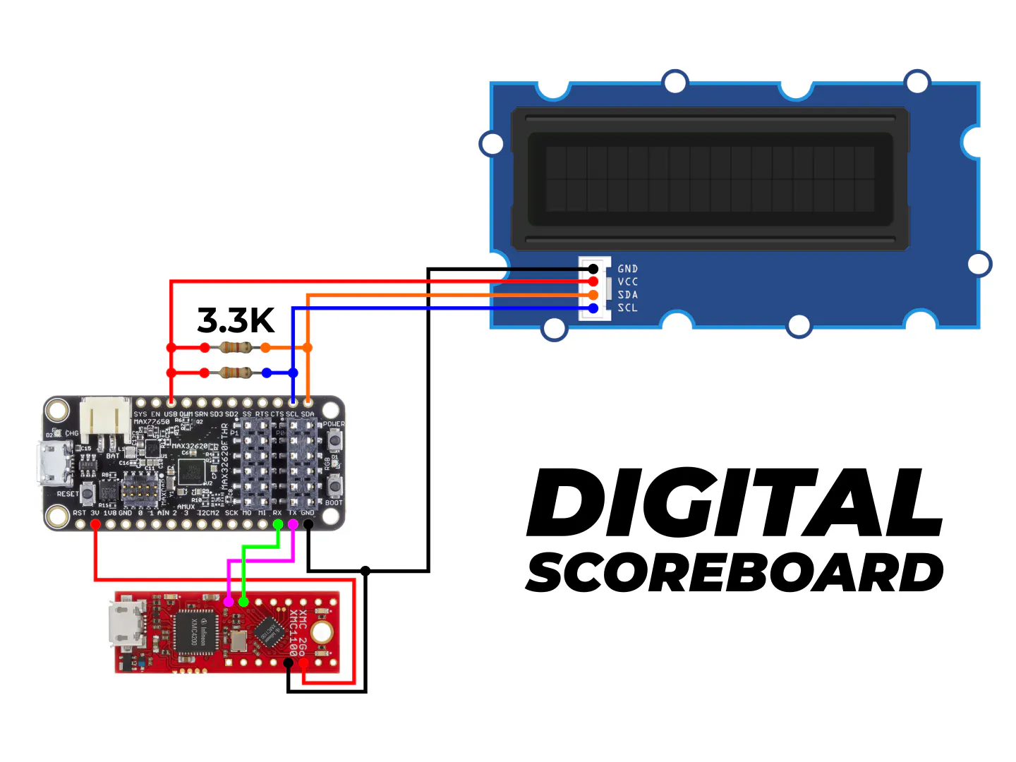
To do that, simply connect the Tx of the XMC2Go to the Rx of the MAX32620FTHR (UART2) and the Rx of the XMC2Go to the Tx of the MAX32620FTHR (Again, UART2), and the grounds. This is how it should look like:
We need a display for the digital scoreboard, and I chose the Grove I2C RGB Display.
To attach it you would simply connect SDA on the display to SDA on the MAX32620FTHR and the same for SCL, along with the ground pin and 5 volts for power. But it won't work like this in this case.
You need to attach 2 (3.3k) pull up resistors connected from the +5v pin to the SDA and SCL lines for the I2C lines to work.
These images will help you with that:
This is a close up of the resistors connected:
And this is the final result, just before testing:
This is a picture of the wiring:
Note: I have connected 3.3v from the MAX32620FTHR to the XMC2Go; this will power up the XMC2Go directly from the MAX32620FTHR. Quoting from the XMC2Go pin-out diagram:
If board is powered through 3.3v pin, it is not recommended to power through USB and vice versa
Once wired properly, just plug in and test. The MAX32625PICO will not be needed now, it was just for uploading the code.
Then it will show this:
This arrow shows the current player, and it changes it's position as you rotate the knob (without pressing it):
Pressing the knob (and keeping it pressed), then rotating it left or right, increases or decreases the score for a player.
Virtually any number of players can be added and the same code can be used for a variety of applications.
To add more players, simply make this modification in the XMC2Go code:
Then add more variables and parse as I did in the MAX32620FTHR code. Look at the attached code and you will get the idea.
For example, if you want 4 players instead of 2, simply change the variable numPlayers to 2 in the XMC2Go code, and use the attached MAX32620FTHR code for 4 players.
Understanding the CodeTo understand how the code works, think of the rotator knob as the unit circle in mathematics.
This gives the angle from 0 to 2π:
angle = pi + Tle493dMagnetic3DSensor.getAzimuth();
Dividing 2π by the number of players gives sectors of equal length for each player.
The XMC2Go takes data from the magnetic sensor, calculates what position the knob is currently on, and based on that determines the current player. When pressing and holding the knob at a specific player's sector (on the unit circle), rotating it will increase or decrease the score.
Scores for each player are stored in an array which is sent over to the MAX32620FTHR by the serial port, where it is parsed and displayed on the Grove RGB LCD.
If you want how fast the score increases or decreasing, adjust this value in the functions increaseScore() or decreaseScore():
tempScore[i] = tempScore[i] + 0.17;
This is in increaseScore() and changing the "0.17" to something higher will change the score more quickly.
For the function decreaseScore() the same happens but this time instead of adding something, you subtract it:
tempScore[i] = tempScore[i] - 0.17;
And this is done in decreaseScore() to make the score stay at 0, if it already is:
     if (tempScore[i] < 0) {
       tempScore[i] = 0;
     }
Just remove it if you want the score to go to negative numbers.
Other than that, this should be enough to modify it for your own use. Feel free to use it in any sports or wherever you need to count score or something, and it will work.
Bonus Feature: Connecting to the InternetSuppose you need to add an improvement to the scoreboard - saving your previous match scores. You use the following modules as listed here in the MAX32620FTHR cheat sheet:
Because I didn't have any of these and ordering would take time. I just decided to use Wiznet's WIZ750SR Serial to Ethernet converter, to connect it to the Internet.
I used the same method as in my other project here for automating your curtains, connecting it to Blynk by using UART0 on the MAX32620FTHR. For configuring the WIZ750SR, just look at my other project, and wiring is also same as in my other project (Tx and Rx pins - UART0), 3.3v and ground. I didn't make any widgets, just tried to connect it to Blynk and it worked perfectly.
So, if you need to use it feel free to use the code below to connect it to Blynk. It won't work until a LAN cable is connected to the WIZ750SR.
#include <Wire.h>
#include "rgb_lcd.h"
#include <BlynkSimpleStream.h>
#define vBUTTON_PIN V0
#define vP1_PIN V1
#define vP2_PIN V2
#define vP3_PIN V3
#define vP4_PIN V4
int input;
int currentPlayer;
int score1 = 0;
int score2 = 0;
int score3 = 0;
int score4 = 0;
int value;
rgb_lcd lcd;
// You should get Auth Token in the Blynk App.
// Go to the Project Settings (nut icon).
char auth[] = "YourAuthTokenHere";
void setup()
{
 // set up the LCD's number of columns and rows:
 lcd.begin(16, 2);
 const int colorR = 255;
 const int colorG = 255;
 const int colorB = 255;
 Serial.begin(9600);
 Serial0.begin(115200);
 Serial2.begin(9600);
 Blynk.begin(Serial0, auth);
 lcd.setRGB(colorR, colorG, colorB);
 lcd.setCursor(5, 0);
 lcd.print("Digital");
 lcd.setCursor(3, 1);
 lcd.print("Scoreboard");
 delay(1700);
}
void loop()
{
 Blynk.run();
 input = Serial2.parseInt();
 if (input == 99999) {
   currentPlayer = Serial2.parseInt();
   score1 = Serial2.parseInt();
   score2 = Serial2.parseInt();
   score3 = Serial2.parseInt();
   score4 = Serial2.parseInt();
 }
 Serial.print(currentPlayer);
 Serial.print(",");
 Serial.print(score1);
 Serial.print(",");
 Serial.print(score2);
 Serial.print(",");
 Serial.print(score3);
 Serial.print(",");
 Serial.println(score4);
 lcd.clear();
 lcd.setCursor(0, 0);
 lcd.print("P1:");
 lcd.print(score1);
 lcd.setCursor(10, 0);
 lcd.print("P2:");
 lcd.print(score2);
 lcd.setCursor(0, 1);
 lcd.print("P3:");
 lcd.print(score3);
 lcd.setCursor(10, 1);
 lcd.print("P4:");
 lcd.print(score4);
 switch (currentPlayer) {
   case 1:
     {
       lcd.setRGB(102, 178, 255);
       lcd.setCursor(6, 0);
       lcd.print("<=");
       break;
     }
   case 2:
     {
       lcd.setRGB(178, 102, 255);
       lcd.setCursor(7, 0);
       lcd.print("=>");
       break;
     }
   case 3:
     {
       lcd.setRGB(255, 102, 102);
       lcd.setCursor(6, 1);
       lcd.print("<=");
       break;
     }
   case 4:
     {
       lcd.setRGB(102, 255, 178);
       lcd.setCursor(7, 1);
       lcd.print("=>");
       break;
     }
 }
}
BLYNK_WRITE(vBUTTON_PIN) {
 value = param.asInt(); // Get value as integer
}
Note: To be honest, I won't be using the Internet connectivity feature. I'm very satisfied with the basic digital scoreboard, but maybe I will modify it in future, but not with Blynk; most probably send timestamped results to Google Sheets.
Final TouchesThese final touches will certainly be great improvements for this design:
- Using a battery. I didn't try this simply because I didn't have a suitable battery at hand. The MAX32620FTHR's extensive power options will certainly help with this.
- A menu to allow the users to select the number of players.
- Using just the magnetic sensor connected to the MAX32620FTHR instead of the XMC2Go kit. That will reduce the cost of the project, and also reduce it's size.
- A larger display.
- A laser-cut or 3D-printed enclosure.
Feel free to share your thoughts or give suggestions on this project.


Comments