


Hardware components | ||||||
| × | 1 | ||||
 |
| × | 1 | |||
 |
| × | 1 | |||
 |
| × | 1 | |||
Software apps and online services | ||||||
 |
| |||||
About: Hello, the author of the project is an Application Engineer of Seeed Studio. It's great to share this project with the Hackster maker community. I hope you like Seeed Studio, a hardware enabler for IoT applications, which provides services that enable IoT developers to quickly prototype... More information about Seeed Studio »
Today(21/6/2016) is the Summer Solstice, It means the scorching summer is coming up. So how about DIY a carry-on UV Detector.
Sometimes I want to know the UV series around me. Activities in the field, for example, I need to know if I should do some protective measures. So, I made this project with Grove - Joint(compatible with Arduino) and some other Grove Modules. The Grove - LED Bar indicates the current UV series.
By the time you’re done with the demo you will gain the following experience:
- Be familiar with Arduino/Grove - Joint;
- Show off the work to your friends.
Now, let’s get started.
Add TipAsk QuestionCommentDownload
Step 1: What Do We NeedGrove - Joint shares many similarities with Seeeduino Lotus/Arduino. It is a mini ATMEGA328 Microcontroller development board. It uses an Atmel ATMEGA328P-MU and CH340. ATMEGA328P-MU is a high performance, low power AVR 8-Bit Microcontroller. CH340 is a USB bus converter chip that can realize a USB to serial interface. Grove - Joint v2.0 has two Grove interfaces included I2C port and two digital I/Os. It else support battery powered. You can do some simple applications with it.
Add TipAsk QuestionCommentDownload
Step 2: The Laser Cut Wooden BoxI regard the this UV detector as a work of art, so we should do some decoration work first. Then my friend from Seeed help me cutting the beautiful wooden box. I guess you don't have a laser cutting at home, you can find some in the hacker space near from you easily. If there's no hacker space nearby, you can try theLaser Cutting Servicesupply by Seeed.
You can download the Design Drawing by clickhere.
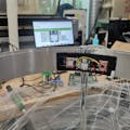
Then we can fix the Grove Modules to the board. As shown in the figure below.
Add TipAsk QuestionCommentDownload
Step 3: Modules ConnectNow we should connect Grove Modules to Grove - Joint. Just as the figure below shows.
Then we should use the GLUE GUN to fix the each side of the box together. As shown in the figure below.
Add TipAsk QuestionCommentDownload
Step 4: Software WorkWe assume you have connected your Grove - Joint and computer well with USB.
- Download demo code at https://github.com/Lee-Kevin/4.A-Carry-on-UV-Detector
- Click “Download zip” button on right side of webpage to download all codes.
- Decompress the downloaded zip files to “C:\Users\Administrator\Documents\Arduino\” and remove “-master” in decompressed file name.
- Launch Arduino IDE.
- Click Sketch>Add file to add UV_Detector.ino file from “C:\Users\Administrator\Documents\Arduino\4.A-Carry-on-UV-Detector/ExampleCode/UV_Detector ”
- Press CTRL +U to upload codes to your board. Wait a while, there will be prompt like following figure.
Congratulations, you have already completed the most of the work.
Add TipAsk QuestionCommentDownload
Step 5: Operation Instruction- Button-Press the button to power on/off the detector.
- Micro USB- To charge the battery or update new code.
Add TipAsk QuestionCommentDownload
Step 6: Make. Invent. Do.This project is made as an Open Source Project. It's a starting point. Let your creativity go wild with the mechanical, electrical and software design. Make the demo your own. Decorate it. Improve the work. No matter what, write a recipe about it.
To share and progress together.


Comments