


Hardware components | ||||||
 |
| × | 1 | |||
 |
| × | 1 | |||
| × | 1 | ||||
| × | 1 | ||||
| × | 1 | ||||
Software apps and online services | ||||||
 |
| |||||
| ||||||
About: Hello, the author of the project is an Application Engineer of Seeed Studio. It's great to share this project with the Hackster maker community. I hope you like Seeed Studio, a hardware enabler for IoT applications, which provides services that enable IoT developers to quickly prototype... More information about seed studio »
Days ago we share our first smart house project, Personal Voice Assistant.
Here share our new smart hourse project, make a humidifier, chich can connect to the Internet so that you can control it on the cloud. Let see what can it do! I bet you will add this IoT humidifier to your home automation after reading our tutorial.
Feature:
- Auto humidification: IoT humidifier will start to spay when it detects the humidity in the air is lower than setting;
- Manual humidification: Press the button to start humidification;
- Remoto humidification: Start humidification in the cloud when you are far away from the humidifier;
- Data record: All the data will be sent to the cloud to store, and you can visit your data by using the view option.
In this tutorial, we will lead you to DIY this IoT humidifier!
Step 1: What Do We Need· Grove - Temperature&Humidity Sensor (HDC1000)
· Grove Breakout for LinkIt Smart 7688 Duo
· Grove – Water Atomization v1.0
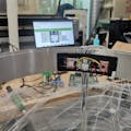
Step 2: WiringNow, we should connect the Grove Modules to the Grove Breakout for Linkit Smart 7688 Duo just as below picture shows.
But the Grove – Water Atomization operating voltage is 5V, the Grove interface on the Grove Breakout board is only 3.3V, so we need to do something change on the cable.
Step 3: Setup the Linkit Smart 7688 DuoThe software work of the IoT Humidifier consists of 2 parts, the code running on Arduino side and the python script running on the LinkIt Smart 7688 side.
I assume you have been familiar with Linkit Smart 7688 Duo, if not, please click here to get started, then go to the MT7688 terminal by SSH or serial.
Modify the configure file to change MT7688 into station mode and connect to the internet.
vi /etc/config/wirelessChange the configure file as below shows.
Change the ssid and key to your own on the red box as the picture shows.
We use the yunbridge for communicating between MT7688 and ATmega32U4, so, enable the yunbridge.
> uci set yunbridge.config.disabled='0'

> uci commit
To have a try ping a website to ensure your LinkIt Smart 7688 Duo have connected the internet well.
ping seeed.ccMediaTek Cloud Sandbox (MCS) is a cloud based data service platform for Internet of Things devices. If you don’t have an account please click https://mcs.mediatek.com/oauth/en/signup to sign up.
MCS has already provided some useful tutorials, you can create the prototype and test device in MCS step by step following here. Then in my project I create a new prototype for Linkit Smart 7688 named IoTHumidifier, then create test device “named my IoT Humidifier” and add three data channels for this prototype they’re Button humi_temperature and Humidity just as picture below shows.
Step 5: Upload the Arduino Code1. Download demo code at https://github.com/Lee-Kevin/AutomaticHumidifier/...
2. Click “Download zip” button on right side of webpage to download all codes.
3. Decompress the downloaded zip files to“C:\Users\Administrator\Documents\Arduino\” and remove “-master” in decompressed file name.
4. Launch Arduino IDE.
5. Click Sketch>Add file to add Humidifier_Arduino.ino file from“C:\Users\Administrator\Documents\Arduino\AutomaticHumidifier\ArduinoCode\Humidifier_Arduino\”
6. Click Tools -> Board and select “Linkit Smart 7688 Duo” and chose the right port, as shown in the picture below.
Step 6: Download the CodeNow, we have already install the requirements, download the code from github. https://github.com/Lee-Kevin/AutomaticHumidifier
cd AutomaticHumidifierNavigate to AutomaticHumidifier and you can find there’re 3 folders, ArduinoCode, Script and Drawings. RouterArduinoCode is the code that should be run on Arduino, Script is the Python code should to be run on Linkit Smart 7688. Now we change directory to AutomaticHumidifier/Script/ and edit the UpdateSensor.py and atomizer.py using vi editor
cd AutomaticHumidifier/Script/
vi UpdateSensor.py

vi atomizer.py
Change the deviceID, deviceKey and dateChannelID to your device. As shown in the following figure.
And then install the dependent package
pip install requestsNavigate to /root/AutomaticHumidifier
cd ~ & cd /root/AutomaticHumidifier/Then setting the startup script.
chmod +x Automatic & mv Automatic /etc/init.d/
/etc/init.d/Automatic enable

/etc/init.d/Automatic start &
And then reboot the router.
rebootWhen the router is reboot done, you have done all the software work.
Step 8: Prepare the Structural ComponentsWhat we need:
· M3*5 bolt——3 pcs
· M3*5+6 stud——3 pcs
· M3 nut—— 3 pcs
· M2*5 stud——8 pcs
· M2*5 nylon bolt——16 pcs
We choose M2*5 nylon bolt here so that you are able to make the bolt shorter when finding them too long to install.
And we suggest using a screwdriver to install, though you can fasten by you hands in most cases.
Step 9: Make a 3d Print ShellNow we are going to make a 3D print shell for the IOT humidifier. Download the stl file attached.
There are several things you should notice here. First, please print 2 parts separately if you are not sure about the 3D printer, or it might be wasteful. And as we need to add water to the cover component, try to use high density material and high accuracy 3D printer. What is more, test if it is leaking after finishing the print. Don't forget to remove the burrs with your knife.
Step 10: Lacer CuttingOur hardware is installed on a 3mm board and placed into the 3D print shell. Download the cdr file attached.
Step 11: Install the Structural ComponentsAfter the lacer cutting, we need to fasten the studs, nuts and bolts to the board as the pictures above. Please note about the installation location.
After the lacer cutting, we need to fasten the studs, nuts and bolts to the board as the pictures above. Please note about the installation location.
Step 12: Install the HardwareFirst, make the wire through the square hole on the board and fasten 3 grove modules as the picture. Then connect them to the breakout for LinkIt 7688 DUO and fasten the breakout to the 3mm studs.
Step 13: Place Into the ShellAfter fastening the hardware to the board, we can place it into the shell now. Don't play hard to get and adjust the wire at any time to make Grove - Button(P) aligning to the hole on the shell as the picture above. Then try to place the cover component into the shell. The notch on the side of shell and cover are for the wire of humidifier.
Step 14: Finish!Now you can add water to the cover component and power LinkIt 7688 DUO. Look, it is spraying now! Try to add some coffee to the cover. :) Then the aroma of coffee will premeate the air.About: Hello, the author of the project is an Application Engineer of Seeed Studio. It's great to share this project with the Hackster maker community. I hope you like Seeed Studio, a hardware enabler for IoT applications, which provides services that enable IoT developers to quickly prototype...


Comments