


Hardware components | ||||||
 |
| × | 1 | |||
Hand tools and fabrication machines | ||||||
| ||||||
| ||||||
About: Hello, the author of the project is an Application Engineer of Seeed Studio. It's great to share this project with the Hackster maker community. I hope you like Seeed Studio, a hardware enabler for IoT applications, which provides services that enable IoT developers to quickly prototype... More information about Seeed Studio »
Step 1: What Do We NeedTranslucent acrylic plate * 10
- Translucent acrylic plate * 10
Transparent acrylic plate * 1
- Transparent acrylic plate * 1
Wrapping paper * 1
- Wrapping paper * 1
Add TipAsk QuestionCommentDownload
Step 2: The Shell PartThe Shell part work is by Nosk, and he is an intelligent designer, you can download his drawings by click here.
1. Laser Cut the board using the Design Drawing. After laser cutting, can be obtained following components.
- Translucent acrylic plate * 10
- Transparent acrylic plate * 1
- Wrapping paper * 1
2. In addition, you also need the following structure:
- M2 nylon rivet * 16pcs
- M3 nylon rivet * 2 pcs
- M3 screw * 20 pcs
Of course, you also need a screwdriver to the screw, then you can install it ~
Add TipAsk QuestionCommentDownload
Step 3: Assembly Work8 More Images
First, build a complete hardware part, as follows
Next, use the M2 rivets fixed the hardware washed on kraft paper
After completing the hardware is fixed, begin installing aluminum shaft.
After completing installation of aluminum shaft, then install translucent acrylic panels.
Note that the two aluminum shafts, one is going to kraft paper fastened together, when the mounting screws are first installed on this side.
To complete the first section of the installation, the subsequent part of the installation in the same way.
Before then press the last two side plates mounted units.
Finally, Use M3 rivets connected end to end.
Add TipAsk QuestionCommentDownload
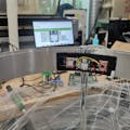
Step 4: Software WorkWe assume you have connected your Xadow - Edison Programmer board to Xadow – Edison well with FFC. Just as the picture below shows.
1. Download the code from Github.
2. Click “Download zip” button on right side of webpage to download all codes.
3. Decompress the downloaded zip files to“C:\Users\Administrator\Documents\Arduino\” and remove “-master” in decompressed file name.
4. Launch Arduino IDE.
5. Click Sketch>Add file to add EdisonBle.ino file from“C:\Users\Administrator\Documents\Arduino\16.EdisonPedometer\Code\Pedometer”
6. Click Tools, and the board select Intel Edison. Just as the below picture shows.
7. Press CTRL +U to upload codes to your board. Wait a while, there will be prompt like following figure: Congratulations, you have already completed the most of the work.
Add TipAsk QuestionCommentDownload
Step 5: Procedure to Autostart the Arduino Sketch on EdisonThere are many ways to do this, but I think the article written by Karthik M. is easy enough. Please put hand on here to learn more.
Add TipAsk QuestionCommentDownload
Step 6: The ResultNow,Reboot your edsion, and the pedometer will work.
Add TipAsk QuestionCommentDownload
Step 7: Make. Invent. Do.This project is made as an Open Source Project. It's a starting point. Let your creativity go wild with the mechanical, electrical and software design. Make the demo your own. Decorate it. Improve the work. No matter what, write a instructable about it.
To share and progress together.


Comments