


Hardware components | ||||||
| × | 1 | ||||
 |
| × | 9 | |||
 |
| × | 2 | |||
 |
| × | 1 | |||
| × | 1 | ||||
Software apps and online services | ||||||
| ||||||
MSP430 Housekeeping MCU Training – UART-Controlled RGB LED
Overview:
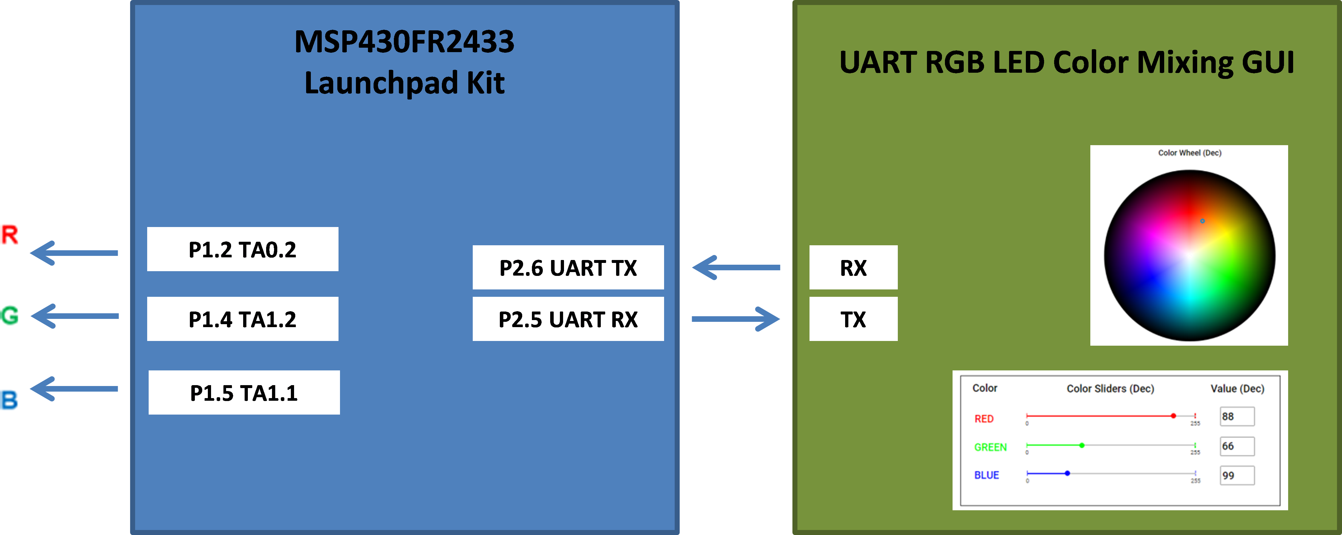
This project uses an MSP430FR2433 LaunchPad and Graphical User Interface (GUI) made on Texas Instruments' GUI Composer tool to showcase mixing any combination of colors on an RGB LED in a matter of minutes! By incorporating simple applications on low-cost secondary MCUs, it can simplify board design and BOM costs in any system.
Materials:
- MSP430FR2433 Launchpad Development Kit (includes Micro-USB cable)
- Common-cathode RGB LED
- 9 female-to-female jumper wires
- Two 1-kΩ resistors
- One 330Ω resistor
- Breadboard (optional, will make setup MUCH easier)
Pre-Work:
1. Create a myTI account on Texas Instruments. You can order free samples, download software tools, and use available online tools and resources with a registered myTI Account. This will allow you to use the RGB LED GUI available in the TI Gallery later on.
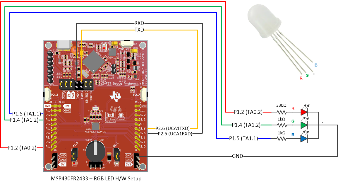
Hardware Setup:
1. Open the MSP430FR2433 LaunchPad development kit and remove the LaunchPad and micro-USB cable.
2. Remove the two jumpers labeled RXD and TXD on the jumper bridge that connects the top and bottom halves of the LaunchPad across the perforated line.
3. Connect the top side of the RXD and TXD pins to P2.5 and P2.6, respectively as shown below.
4. Now we will connect the RGB LED circuit to the LaunchPad. We will follow the schematic below and connect each pin of the LED one at a time. Notice in the RGB LED on the top right corner that the common cathode (-) pin is longer than the other pins. Take your time connecting the jumper wires to the resistors and LED since the leads may easily disconnect.
5. Let’s begin with the Red (R) of the RGB LED. Connect a jumper wire from P1.2 on the LaunchPad to one end of the 330Ω resistor. Connect the other end of the resistor to the “R” pin of the RGB LED as shown below.
6. Next, we will connect the Green (G) pin of the RGB LED. Connect a jumper wire from P1.4 on the LaunchPad to one end of a 1kΩ resistor. Connect the other end of the resistor to the “G” pin of the RGB LED as shown below.
7. Next, we will connect the Blue (B) pin of the RGB LED. Connect a jumper wire from P1.5 on the LaunchPad to one end of the other 1kΩ resistor. Connect the other end of the resistor to the “B” pin of the RGB LED as shown below.
8. To complete the circuit, use the last jumper wire to connect the common cathode (-) pin of the RGB LED to any ground pin (GND) on the LaunchPad as shown below.
9. Finally, connect the micro-USB cable from your computer to the MSP430FR2433. The green LED on the LaunchPad should light up.
Launching the GUI:
1. Access the RGB Color Mixing Demo on the TI Gallery.
2. Close the README.md once it pops up on the screen. The GUI will begin to automatically download the RGB LED Color Mixing firmware onto the MSP430 device. The “Flash Successful!” message will appear after a few seconds on the bottom left hand corner. Once the “waiting for data…” message appears, you are ready to start using the GUI to mix colors!
Using the GUI:
You can use Color Sliders, Number Boxes, or Color Wheel to choose what amounts of Red, Green, and Blue light you want to mix in the RGB LED. When you use any of the features to mix the color, the other features will automatically adjust to the values and the RGB LED will output the mixed color in real time.
The intensity ranges from 0 to 255 in value, which means there are a total of 256 possible values for each color. That means there are 2563 or over 16 million possible colors to produce! The higher in value of the color, the more intense that hue is in the mixed color.
Here are some common color “coordinates”/values:
Color Sliders – Drag the markers or click on the location of the slider to set a value for each color.
Number Boxes – Type in a number between 0-255 for a color. Press “Enter” when finished typing the number.
Color Wheel – Click or drag the marker on the wheel to automatically send the RGB values to the LED and display that color real-time! Sometimes you may need to click the same spot twice to refresh the values to the correctly chosen ones.
Resources
Want to learn more about how this example works? Check out the resources below to find more information in regards to RGB Color Mixing:
- RGB LED color mixing application brief
- RGB LED color mixing code (Code Composer Studio required)
For more MSP430 Housekeeping examples, such as Real-Time Clocks and Wake-Up Controllers, visit the MSP430 Housekeeping Page.
RGB LED Schematic


_3u05Tpwasz.png?auto=compress%2Cformat&w=40&h=40&fit=fillmax&bg=fff&dpr=2)

Comments