

Hardware components | ||||||
 |
| × | 1 | |||
| × | 1 | ||||
| × | 1 | ||||
| × | 1 | ||||
| × | 1 | ||||
| × | 1 | ||||
| × | 1 | ||||
Software apps and online services | ||||||
 |
| |||||
Hand tools and fabrication machines | ||||||
| ||||||
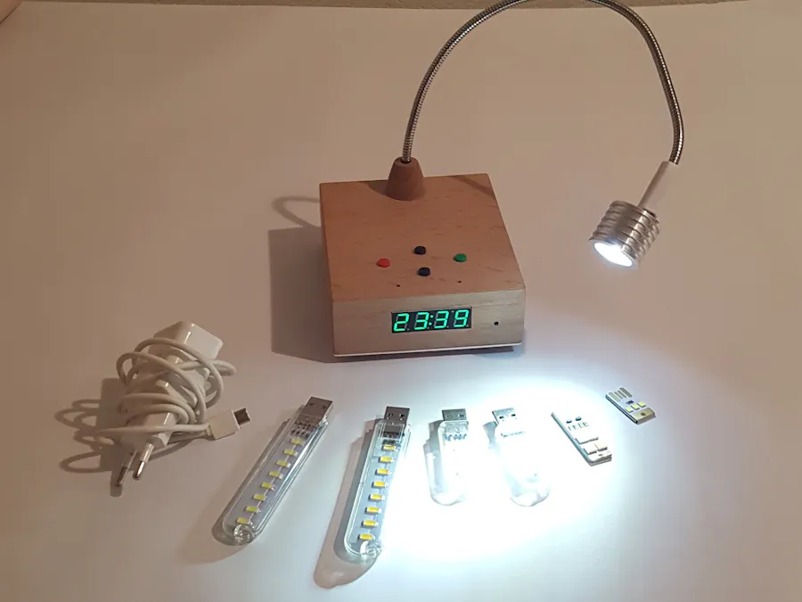
Whether for crafting or reading, a compact, mains-independent LED light, universal and versatile insertable, is a valuable helper.
First of all, I am not a trained electronicsengineer or programmer, the main idea was to learn as much as possible withthis project:Plan, PCB manufacturing, schematic drawing, layout design, writing codes, etc.
I made the first version of such a lamp years ago, very simple construction:
4 AA batteries a 3Watt LED and two brightnesslevels through a voltage divider, very high power dissipation! I was not sohappy with it, but it worked.
The second version came after that and was a bitbetter, a transistor and a potentiometer were the improvements, I was able todim the brightness nicely, very small power losses and a long life with only 4AA batteries.
But it is even better
Version 3
And that was the idea.
What must she do? The creativity with the help of amicrocontroller are probably no limits.
My wishes:Battery operated, rechargeable,Digitally dimmable light via PWM,Timedisplay. Different light temperatures: warm, cold, headlights. Realized with 5Volt USB-LED-Attachments, buttons with multiple functions.And all on Arduino basis, so with an MCU.
Wonderful and as I am, I also had the idea of thefinished lamp in front of my eyes and then went straight to work.Normally, a device is first planned then gradually expanded.For me it was a little different, I had the finished device in front of myeyes, before it was finished.And so I built from outside to inside, actually you should reverse the way toavoid problems (eg lack of space).So I first built the case and then I had to look like I make all the hardwareas compact as possible to get everything in.
For me, technology and electronics is an expressionof artistic creativity.Most important is that it had to look nice and it should be versatile.I wanted to make something elegant and gave me a lot of effort.
After planning and drawing the circuit diagram, itwent, without the help of an autorouter, to the board layout, which can be verylengthy, believe me. I learned a lot while doing the most important thing:testing, testing and retesting!
Until I pass the fun of testing.And you are sure that everything works well together, and there are noconflicts between the functional groups. Playing through all possible causes, sources of error and usage scenarios isalso an important step in the test phase.
Only then can you start producing.
Function Description:
Since the luminaire should be rechargeable, I hadto opt for a charging method. Only the charger of my mobile phone came to mymind. The battery capacity was the second criterion. They should last for aslong as possible. I chose two 18650 Li-ion batteries, 8.4V!
I had to come to the 8.4 volts, I had only 5 voltsat the entrance
So I had to bring them to about 8 volts, the onlything that comes to my mind was a StepUp Converter, you get these finishedmodules almost from everywhere.
Continue goes to the battery charging unit, this isa finished 2S-charging module. In order to save the batteries and the circuit, I have also decided for a BMS. And from the BMS, it goes with 8.2 volts (atfull charge) directly to the motherboard.This again is a problem because the USB LED attachments can only tolerate 5volts, I had to see how I managed that, the light is not yet a heater at thesame time. It came spontaneously or even after lengthy consideration, only twoways to resolve the problem:Fixed current limit or power losses. Since I wanted to get the highest possibleperformance, it was a problem when I set a transistor to 500mA collectorcurrent. If I connect an LED attachment, e.g. 150mA power needed, the voltageon this again increases. So I decided on the second option. Since the voltageon the MOSFET driver drops by about 0.6 volts, I still had good 7.5 volts onthe LED. I opted for two diodes in series so I could break the voltage down toabout 6 volts, that's manageable.
I know 6 volts and 400mA on two diodes... Andagain power losses, but I had no better idea. In any case, that was the onlyway to drive my project forward (measured temperature at the diodes about 100 °C).I have provided the diodes with a cooling housing and the temperature droppedeven more.
The board is actually quite simple:
To switch the device on or off, I used the ideafrom the "EEVblog # 262-World's Simplest Soft-Latch Power SwitchCircuit". Its circuit comes with just a push button and can completelyswitch or disconnect, great!
Then it goes on to the 5 Volt voltage regulator forthe MCU. The controller is an ATtiny85, I found a ATmega328 a bit oversized. Thecontroller reads 3 keys and controls the display digitally and the LED via PWM.
Das Display istauch ein fertiges Modul, das die Zeit, Temperatur und sogar die Spannunganzeigen kann. Genau das, was ich brauchte. Der PWM-Ausgang wird über einenOptokoppler zum Logikpegel-MOSFET-Treiber weitergeführt. The digital output for the display goes to thetransistor and switches the display to GND via the collector.
Schematic and Block Diagram:
Better quality in the appendix.
That's it.
PS: Do not be surprised about my english, google has translated it
New option for hot days:
Replica LTE version:


Comments