


Hardware components | ||||||
_ztBMuBhMHo.jpg?auto=compress%2Cformat&w=48&h=48&fit=fill&bg=ffffff) |
| × | 1 | |||
 |
| × | 10 | |||
 |
| × | 11 | |||
 |
| × | 1 | |||
BEGINNER PROGRAM AND CIRCUIT
Before getting to the main purpose of this project, as it is for beginners and I had a few problems related to this when I started, here are some things crucial to understand for when you plug in boards.
Let us say you have two UNO R3 boards and you plug in the first one. When you first plug it in you may have to identify which port/COM it is attached to in order to upload to it. That is normal practice. Let us say it connects (on Windows) to COM10.
You complete the programming and circuit for it and put that board aside.
Now you plug in your second (or any subsequent) board. It is almost certain that the Arduino programming console (the IDE), will reconnect (but it sometimes needs a 'reminder' click) as the IDE (where you write your program) finds the board.
You still might find that your board does not receive data. This is probably because, if you look down at the bottom right hand corner of the window, you will see it still showing the last COM number, COM10, in this case, but each board gets it's own COM number.
Now go into the Menu bar, "Tools" then "Port". Click on Port and a flyout will eject to one side, and will show something like, "COM5 Arduino/Genuino UNO". So it would be showing COM5 in here and the console still has COM10 in the bottom right hand corner, so that is where the present problem lies.
Now click on the COM5 in the flyout and the IDE will reconnect with the window itself and you will see the COM5 appear in the bottom right corner of ALL your open Arduino IDE windows. Problem solved.
There will be other problems, but this will enable you to realise you can solve them by taking the time to learn IDE operations as you go along.
NOW TO THE PRESENT PROJECT
I was considering how we understand a circuit and it's program.
In my first project, Flash_BRIGHT, I presented both a new circuit layout and a new program sequence.
For a beginner ((which I was, at the time I did that project) looking at that first project, if the circuit is easy to build, the program is not necessarily easy to follow.
Programmers shrink programs to the smallest size they can, to save memory space and allow fast and efficient operation, and it is a good habit to get into, but that is the point, 'habit'.
We can only gain a habit when we have enough knowledge and experience to bypass the long route.
I hope this project will fast-track newbies into following the processes of both circuit and program, at least for this type of generic project.
Hence, when you see that this project's program is much larger than my last project, Flash_BRIGHT, you will nevertheless, I hope, have a more than excellent chance of following how it works.
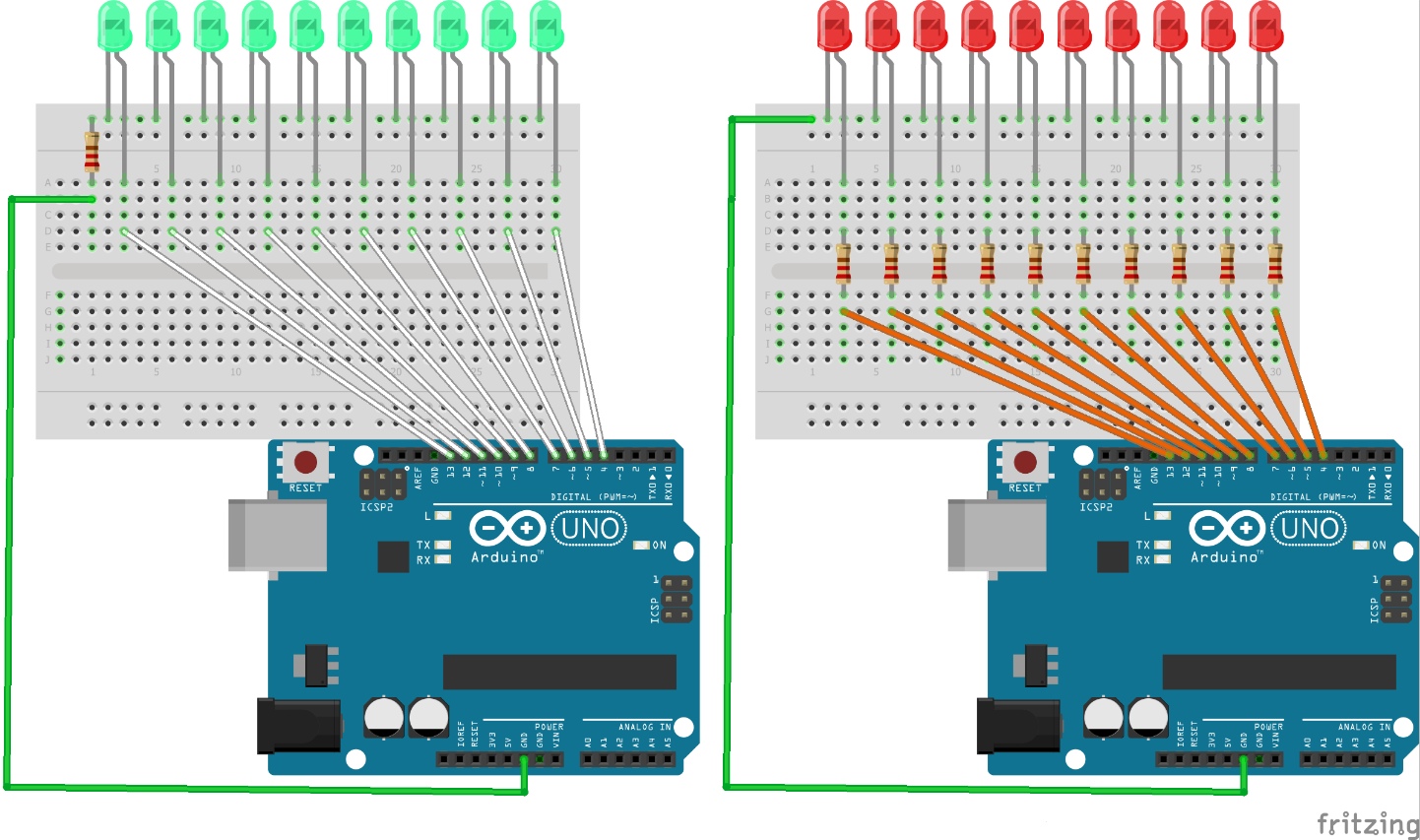
It lights 10 LEDs in back-and-forth pseudo-motion , whichever circuit model you use, as shown below. It is worthwhile building each circuit as the circuits operate exactly the same, but demonstrate a slightly different principle of using ground (GND).
The reason I simplified it for Flash_BRIGHT is 'only' because a single LED is lit at any time. If I was lighting two or more, and/or controlling motors/sensors at the same time, then I would have to be quite serious about not putting in one resistor just because it looks as though I could.
So, this Code is fairly long, for what it does, but will enable you properly see what is happening and why, and relate this information to either circuit.
Have a look around at other "Larsen scanner/Knight Rider" circuits, after you've done this one and taken a look at the Flash_BRIGHT code, and you will then see that there are lots of ways of programming the same or similar circuits.
This beginner program will help you understand other programs easier.


Comments