


Hardware components | ||||||
 |
| × | 2 | |||
| × | 1 | ||||
Software apps and online services | ||||||
| ||||||
 |
| |||||
| ||||||
Hand tools and fabrication machines | ||||||
_LWNORVejBN.png?auto=compress%2Cformat&w=48&h=48&fit=fill&bg=ffffff) |
| |||||
I aim to achieve better wireless performance. However, implementing 5G connectivity alongside other tasks on a single XIAO ESP32-C5 would result in excessive resource overhead. For this reason, I adopted two XIAO ESP32-C5 boards for the project.
One works as the main control MCU to drive the ILI9341 LCD display, leaving room for future functional expansion. The other functions purely as a communication module dedicated to wireless transmission. This communication unit can also be replaced with other AT modules later on.
The setup involves quite a few steps, yet the whole process is interesting. I currently separate the control part from the communication part, but I haven't built a proper practical case for home use. If you have any ideas, feel free to leave a comment or send me an email. Your suggestions will be greatly appreciated
Flash AT firmware to XIAO ESP32-C51. Set up the ESP-IDF compilation environment
I compile firmware with ESP-IDF on Windows. Espressif provides an all-in-one compilation environment, so there is no need to build firmware under Linux. You may refer to the guide below for environment setup steps:
2. Pull the AT firmware
git clone https://github.com/espressif/esp-at.gitAfter obtaining the AT firmware, further modifications are required. This process carries risks. I recommend using a spare XIAO ESP32-C5 or other XIAO ESP32 series boards for this operation. Flashing the pure AT firmware will disable the USB serial port. You can only restore the board by reflashing a blank program via the J-Link pads on the bottom.
2.1. Modify AT communication pins
The default AT communication pins are TX (GPIO23) and RX (GPIO24), which correspond to D4 and D5 on XIAO. We need to reassign them to TX (GPIO11 / D6) and RX (GPIO12 / D7).
Open the cloned folder, navigate to the path: \esp-at\components\customized_partitions\raw_data\factory_param\, locate the file factory_param_data.csv, edit the configurations for ESP32-C5 and save the changes.
//PLATFORM_ESP32C5,ESP32C5-4MB,"4MB, Wi-Fi + BLE, OTA, TX:23 RX:24",4,78,1,1,13,CN,115200,23,24,25,26,1

PLATFORM_ESP32C5,ESP32C5-4MB,"4MB, Wi-Fi + BLE, OTA, TX:11 RX:12",4,78,1,1,13,CN,115200,11,12,25,26,1
2.2 Compile the Firmware
Launch the pre-configured ESP-IDF development environment, i.e., open ESP-IDF 5.5 PowerShell.
Open the target file
cd ~/esp-atSelect the target chip and flash the firmware with tools
idf.py set-target esp32c5

idf.py build

idf.py flash monitor1. Install the PlatformIO extension in VS Code for compilation. Refer to the link below for the guide: Platform IO with Seeed Studio XIAO ESP32-C5
2. Edit the platform.ini file
[env:seeed-xiao-esp32-c5]
platform = https://github.com/Seeed-Studio/platform-seeedboards.git
board = seeed-xiao-esp32-c5
framework = arduino
monitor_speed = 115200
lib_deps =
    adafruit/Adafruit GFX Library
    adafruit/Adafruit ILI9341
3. Code Development
Adjust the corresponding pins to adapt to the ILI9341 display, including SPI control pins and communication pins for the AT module. The macro definitions are shown below:
/** UART1 RX pin - receives data from AT module TX */
#define UART_RX_PIN D7       // GPIO12
/** UART1 TX pin - sends data to AT module RX */
#define UART_TX_PIN D6       // GPIO11
/** Baud rate matching AT firmware default */
#define UART_BAUDRATE 115200

// TFT LCD SPI pin mapping (ILI9341)
#define TFT_BL D0           // Backlight control
#define TFT_CS D2           // Chip select
#define TFT_DC D4           // Data/command
#define TFT_MISO D9           // Master-in slave-out
#define TFT_MOSI D10          // Master-out slave-in
#define TFT_SCLK D8           // SPI clock
#define TFT_RST -1           // Reset (tied to hardware reset)
3.1 Learn the basics of AT commands
Understanding AT commands helps you send proper instructions to the AT firmware to establish network connections.
// Test
AT
//back
OK

// Clean
AT+CWQAP
// clean
WIFI DISCONNECT OK

// Scan
AT+CWLAP
//back
wifi

//Connect
AT+CWJAP="Your_SSID","your_password"
//back
WIFI CONNECTED
WIFI GOT IP

//Check the Connect
AT+CWJAP?
// back
wifi_SSID & MAC ipaddr

//check the wifi ipaddr
AT+CIPSTA?
//back
IP Addr
gateway
mask
For more details, please refer to the resources : Wi-Fi AT Commands
4. Compile and upload the firmware
You can find the full program in my repository: CYD_XIAO_ESP32-C5
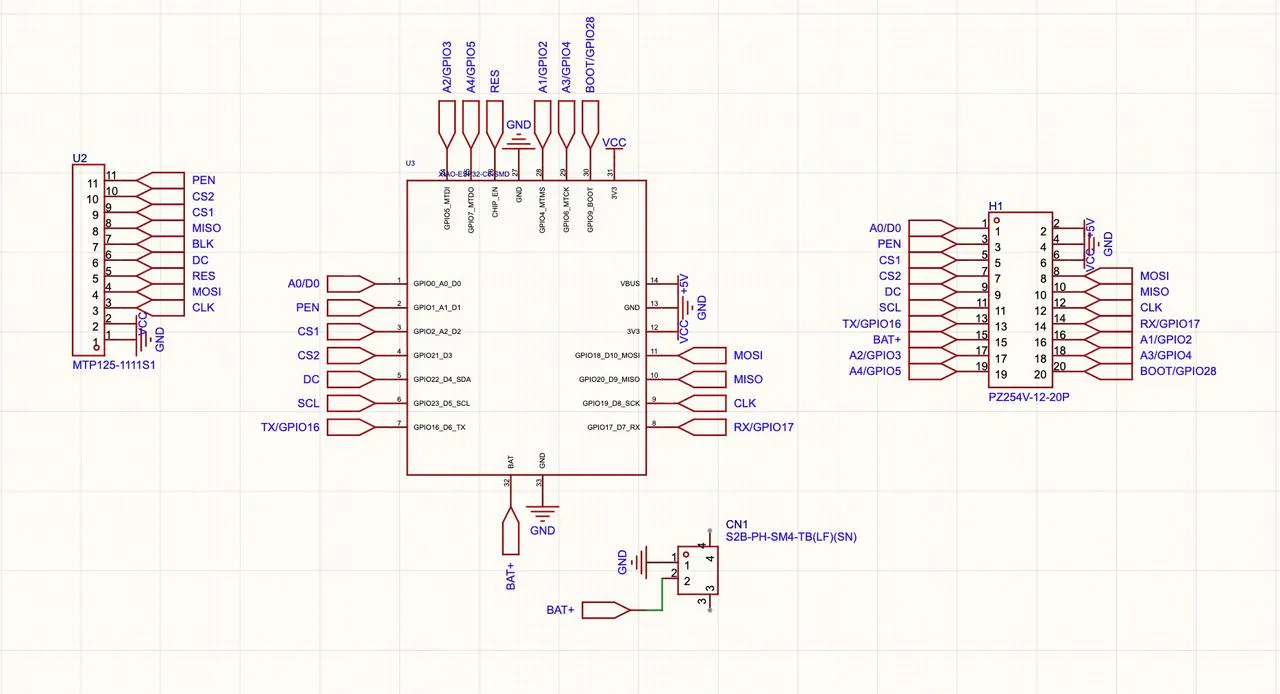
I used a custom PCBA for wiring to make a finished product. You can also use jumper wires instead. See the wiring sequence below.Finished PCBA
XIAO AT Moudels  -> XIAO ESP32-C5
/** UART1 RX pin - receives data from AT module TX */
UART_RX_PIN(D6)  -> D7       // GPIO12
/** UART1 TX pin - sends data to AT module RX */
UART_TX_PIN(D7)  -> D6       // GPIO11


ILL9341  ->   XIAO ESP32-C5
TFT_BL   ->   D0           // Backlight control
TFT_CS   ->   D2           // Chip select
TFT_DC   ->   D4           // Data/command
TFT_MISO ->   D9           // Master-in slave-out
TFT_MOSI ->   D10          // Master-out slave-in
TFT_SCLK ->   D8           // SPI clock
TFT_RST -1           // Reset (tied to hardware reset)
Finished PCBA
The screen refreshes line by line and displays the status of Wi-Fi connection via AT commands. The overall performance works well.


Comments