

Hardware components | ||||||
| × | 1 | ||||
Software apps and online services | ||||||
 |
| |||||
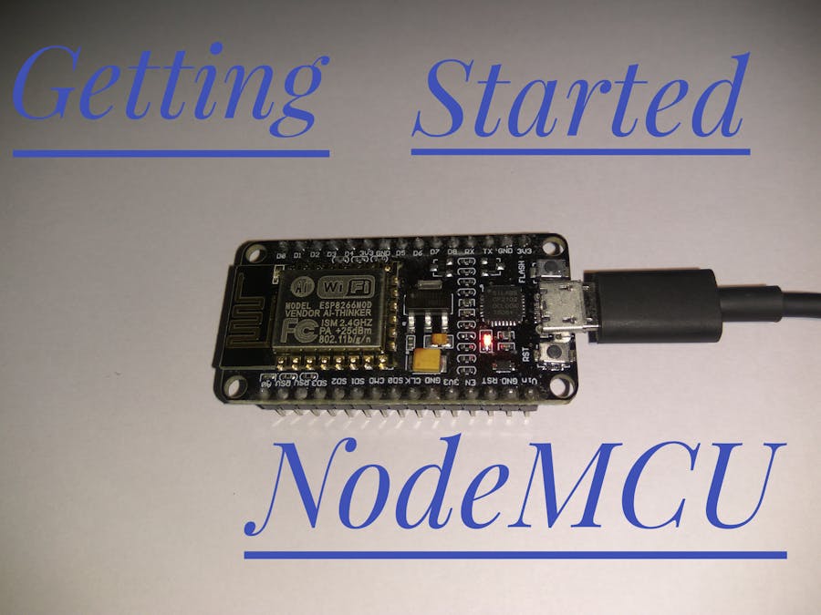
In this tutorial I'm sharing how you can get started with NodeMCU (ESP8266) with Arduino IDE. This tutorial is for beginners who are just getting started. NodeMCU is just like Arduino with on-board Wifi, so you can take your projects online. To know more about NodeMCU visit its official website here.
I will be sharing more projects based on this so make sure to follow me if you are interested.
So lets get started.
Step 1: THINGS YOU NEED :-- Breadboard. (Best buy links : US, UK)
That's all you will need refer the best buy links if you don't already have the Board.
Once you have the required things. Move to the next step.
Step 2: SETTING UP THE IDE :-- First Download and Install Arduino IDE.
- Goto >> Files >> Preferences and paste following Link in "Additional board manager URL's"
"http://arduino.esp8266.com/stable/package_esp8266com_index.json" (Without the quotes)
- Click ok, Now Goto >> Tools >> Board >> Board Manager.
- Scroll down to find ESP8266 and click on install.
This will add all the ESP boards to the IDE.
Now to recognize the Board in computer you have to install CP210X Drivers. It is very simple. Just visit the link and download the version compatible to your device.
now you have to select the correct board, Here I have used NodeMCU 1.0 (ESP-12E Module).
After selecting the board follow settings below :-
- Flash Size : "4M (3M SPIFFS)"
- Debug Port : "Disabled"
- Debug Level: "None"
- IWIP Variant: "V2 Lower Memory"
- CPU Frequency: "80Mhz"
- Upload Speed: "921600"
- Erase Flash: "Sketch On"
- Port : "COM port available" (where the device is connected should show up)
Now you can upload your sketch on the board.
(Refer the pictures for Details.)
Step 3: UPLOADING THE SKETCH :-
Now that the IDE is setup for NodeMCU you can test it by uploading an Example sketch as follows :-
- In IDE Goto >> Files >> Examples >> ESP8266
- Select the Blink Example and upload it.
The on board LED should start to blink. That means you successfully programmed the board. The on board LED is connected to pin D0 of NodeMCU. You can add external LED to Pin D0.
Now for you to work with NodeMCU you have to know the pin outs and Arduino to ESP8266 Pin mapping.
Here I have listed the NodeMCU's pin and corresponding Arduino pins :
- D0 = 16
- D1 = 5
- D2 = 4
- D3 = 0
- D4 = 2
- D5 = 14
- D6 = 12
- D7 = 13
- D8 = 15
- D9 = 3
- D10 = 1
So to use pin D0 of NodeMCU you have to use Pin 16 in Arduino IDE.
If you have any doubts, you can ask in the comments.
In next tutorial I will show you how you how you can control LED over Internet from any where in the world. Check it out here.

Comments