


Hardware components | ||||||
 |
| × | 1 | |||
Software apps and online services | ||||||
 |
| |||||
## Project Overview
This project documents the complete development process of a custom BLDC (Brushless DC) motor controller PCB — from initial schematic design through to turnkey PCB assembly and functional testing.
The board is designed for industrial automation applications requiring precise speed and torque control, compact form factor, and reliable thermal management.
## Design Specifications
- Input voltage: 24–48V DC
- Continuous current: 20A
- PWM frequency: up to 20kHz
- Layer count: 4-layer PCB
- Board size: 95×75mm
- MCU: STM32F4 series - Gate driver: DRV8301 (Texas Instruments)
- Protection: overcurrent, overvoltage, thermal shutdown
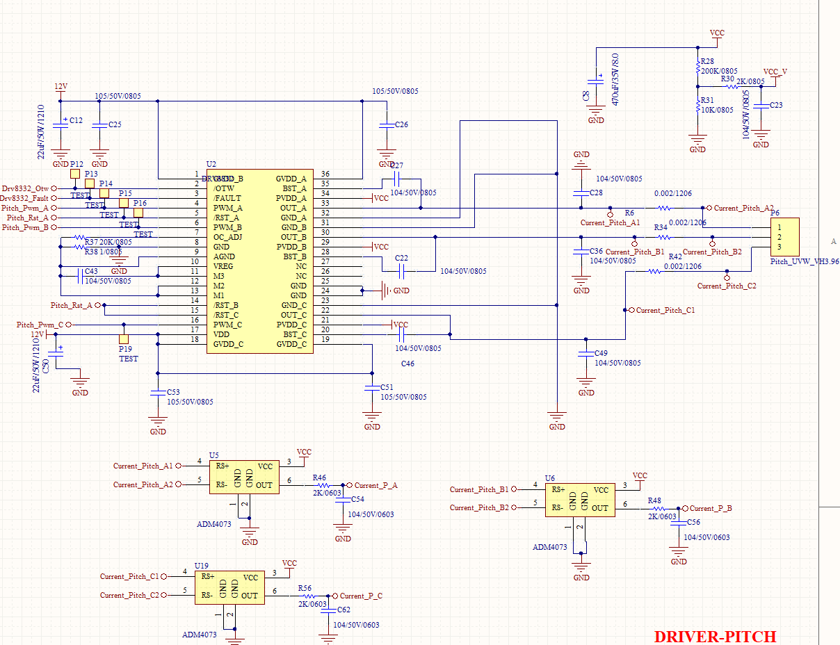
## Step 1 — Schematic Design
The schematic was designed in Altium Designer, covering:
- Power stage (3-phase half-bridge topology) - Gate drive circuit with bootstrap capacitors - Current sensing via low-side shunt resistors
- STM32 MCU with SPI/UART interface - Protection circuits for shoot-through prevention Key design decision: using a dedicated gate driver IC (DRV8301) instead of discrete components simplified the design and improved reliability significantly.
## Step 2 — PCB Layout
Critical layout considerations for this board:
**Power loop minimization:
** The high-current path between the bulk capacitors, MOSFETs, and motor output was kept as short as possible to reduce parasitic inductance and switching noise.
**Thermal management:
** MOSFETs were placed on the edge of the board with exposed copper pours connecting to the aluminum enclosure for heat dissipation. CFD thermal simulation confirmed safe operating temperatures at full load.
**Signal integrity:
** Gate drive traces were kept short and matched in length. Analog current sense traces were routed away from switching nodes to minimize noise coupling.
## Step 3 — DFM Review & Fabrication
Before sending to fabrication, a full DFM (Design for Manufacturability) review was conducted:
- Minimum trace/space: 5mil/5mil - Via size: 0.3mm drill / 0.6mm pad - Impedance-controlled traces for SPI lines (50Ω)
- Panelization: 2×3 array with V-score separation The board was fabricated as a 4-layer stackup:
- Layer 1: Signal + components
- Layer 2: Ground plane
- Layer 3: Power plane (48V / GND split)
- Layer 4: Signal + thermal copper
## Step 4 — PCB Assembly (PCBA)
Turnkey assembly was handled at our facility in Tianjin, China:
- SMT paste printing + automated pick-and-place
- Reflow soldering (lead-free, RoHS compliant)
- AOI (Automated Optical Inspection) after reflow
- Manual soldering for through-hole connectors - Functional test: motor spin-up, current measurement, thermal check at full load First-pass yield: 98.5%
## Results
The completed motor controller successfully drives a 400W BLDC motor with smooth torque control and thermal performance within spec at ambient temperatures up to 50°C.
## About TJHXPCB
We are a PCB design and assembly manufacturer based in Tianjin, China, providing one-stop services from schematic design to box-build assembly. If you are working on a similar motor controller project or need a reliable PCBA partner, feel free to reach out:
🌐 Website: https://tjhxpcb.com/bldc-motor-controller/
🌐 PCB Assembly: https://tjhxpcb.com/pcb-assembly/
📧 Email: sales@tjhxpcb.com


Comments