


Hardware components | ||||||
 |
| × | 1 | |||
 |
| × | 1 | |||
Software apps and online services | ||||||
_4YUDWziWQ8.png?auto=compress%2Cformat&w=48&h=48&fit=fill&bg=ffffff) |
| |||||
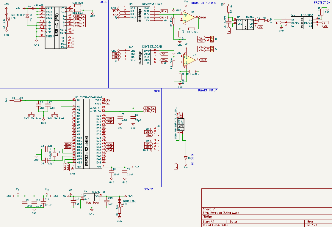
This is the PCB I designed for our combat robotics team, competing in the UK Antweight category. The rules limit robots to a maximum weight of 150 g and require them to fit within a 100 mm × 100 mm footprint (approximately a 4-inch cube).
To meet these tight constraints, I aimed for a compact yet hand-solderable layout, selecting 0805-sized SMD components throughout. By using a six-layer stackup, I dedicated inner layers to solid power and ground planes, which minimized the board's overall size while improving current handling and reducing noise.
The DesignThe core processor is the ESP32-MINI-1 module, chosen for its small footprint, strong performance, and integrated Wi-Fi capabilities. It drives a pair of DRV8231DDAR H-bridge motor drivers (from Texas Instruments), which control the brushed DC motors. Current-sense amplifiers connected to the H-bridges provide feedback to the ESP32, enabling basic monitoring of motor load and performance.
Power for the ESP32 comes from one of two sources: a USB-C connector (primarily for programming and debugging) or a LiPo battery (the typical runtime supply). In both cases, the input voltage is either 5 V (from USB) or a nominal 3.7 V (from the LiPo). Since the ESP32-MINI-1 requires a supply voltage in the 3.0 V to 3.6 V range, the design includes an LDO regulator that steps down the input to a stable 3.3 V for the module and other logic-level components.
For safety, the board incorporates over-current protection for the LiPo battery. Over-charge and over-discharge safeguards are unnecessary here, as charging occurs externally and is not handled on-board.
The PCB

_Ujn5WoVOOu.png?auto=compress%2Cformat&w=40&h=40&fit=fillmax&bg=fff&dpr=2)


Comments