


Hardware components | ||||||
 |
| × | 1 | |||
 |
| × | 2 | |||
 |
| × | 1 | |||
| × | 2 | ||||
 |
| × | 1 | |||
 |
| × | 1 | |||
 |
| × | 1 | |||
 |
| × | 1 | |||
 |
| × | 1 | |||
 |
| × | 1 | |||
 |
| × | 1 | |||
 |
| × | 1 | |||
 |
| × | 15 | |||
Software apps and online services | ||||||
 |
| |||||
 |
| |||||
Hand tools and fabrication machines | ||||||
 |
| |||||
 |
| |||||
 |
| |||||
 |
| |||||
Electricity wastage is a common problem in homes, classrooms, offices, and public places. Often lights and fans remain switched ON even when no one is present in the room. This results in unnecessary power consumption and reduces the lifespan of electrical appliances.
To solve this issue, we designed a Smart Room system that automatically controls electrical appliances based on the number of people inside a room. The system counts the number of persons entering and leaving using infrared sensors and automatically switches ON the lights when someone enters and switches them OFF when the room becomes empty.
This system can be used in places like classrooms, conference halls, offices, shopping malls, and homes where energy efficiency and automation are required.
Concept of Smart RoomThe Smart Room system works on the concept of a digital visitor counter combined with automatic appliance control.
Two infrared sensors are placed near the door. These sensors detect the movement of people entering or leaving the room.
When a person enters the room, the counter increments.
- When a person enters the room, the counter increments.
When a person leaves the room, the counter decrements.
- When a person leaves the room, the counter decrements.
The number of people present inside the room is displayed on a 16×2 LCD display.
- The number of people present inside the room is displayed on a 16×2 LCD display.
If the count is greater than zero, the lights and appliances turn ON.
- If the count is greater than zero, the lights and appliances turn ON.
If the count becomes zero, the lights automatically turn OFF.
- If the count becomes zero, the lights automatically turn OFF.
This system is controlled by the ATmega328 microcontroller, which processes the signals from the sensors and controls the relay connected to electrical appliances.
The working of the Smart Room system involves three main stages:
1. Person DetectionTwo infrared sensors are installed near the door. These sensors detect the interruption of IR beams when a person crosses the doorway.
One sensor detects entry and the other detects exit.
2. Counting LogicThe microcontroller continuously monitors signals from both sensors.
If the entry sensor is triggered, the counter value increases.
- If the entry sensor is triggered, the counter value increases.
If the exit sensor is triggered, the counter value decreases.
- If the exit sensor is triggered, the counter value decreases.
The microcontroller controls a relay module connected to electrical appliances.
If count > 0 → Relay ON → Lights ON
- If count > 0 → Relay ON → Lights ON
If count = 0 → Relay OFF → Lights OFF
- If count = 0 → Relay OFF → Lights OFF
The LCD display continuously shows the number of people inside the room.
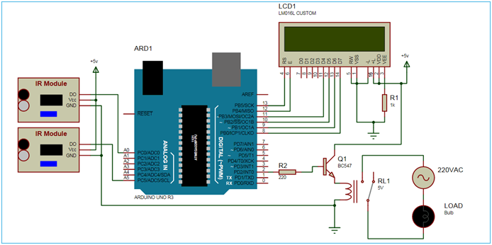
Block Diagram Explanation
The block diagram of the Smart Room system consists of the following major components:
Power Supply Unit – Provides regulated 5V DC supply to the circuit.
- Power Supply Unit – Provides regulated 5V DC supply to the circuit.
IR Sensors – Detect entry and exit of people.
- IR Sensors – Detect entry and exit of people.
ATmega328 Microcontroller – Processes sensor signals and controls output.
- ATmega328 Microcontroller – Processes sensor signals and controls output.
LCD Display – Displays the number of people inside the room.
- LCD Display – Displays the number of people inside the room.
Relay Module – Controls electrical appliances like lights or fans.
- Relay Module – Controls electrical appliances like lights or fans.
AC Appliances – Loads that are automatically controlled by the system.
- AC Appliances – Loads that are automatically controlled by the system.
The microcontroller acts as the brain of the system and coordinates the operation of all components.
Power Supply SystemThe circuit requires a regulated 5V DC power supply for proper operation.
The power supply section consists of the following components:
Step Down Transformer
- Step Down Transformer
Bridge Rectifier
- Bridge Rectifier
Filter Capacitor
- Filter Capacitor
Voltage Regulator (7805)
- Voltage Regulator (7805)
The transformer converts 230V AC mains supply into 12V AC which is suitable for the circuit.
The bridge rectifier converts AC voltage into DC voltage using four diodes arranged in a bridge configuration.
📷 Insert Image – Bridge Rectifier
The capacitor smooths the pulsating DC output of the rectifier and reduces ripple in the output voltage.
The 7805 voltage regulator provides a stable 5V DC output required for the microcontroller and sensors.
Infrared sensors are used to detect the movement of people entering or leaving the room.
The sensor system consists of:
IR Transmitter
- IR Transmitter
IR Receiver
- IR Receiver
The IR transmitter emits infrared radiation which is invisible to the human eye.
IR Transmitter Circuit Diagram
We are using TSOP1738 for receiver, so we need to generate the modulated IR of 38 kHz. You can use any TSOP, but you need to generate IR of respective frequency as TSOP. So we are using 555 timer in Astable mode to oscillate the IR at 38 KHz frequency. As we know oscillation frequency of 555 timer is decided by resistor R1, R2 and capacitor C1. We have used 1k R1, 20K R2 and 1nF capacitor to generate the frequency of approx. 38 KHz. It can be calculated using this formula: 1.44/((R1+2*R2)*C1).
Output Pin 3 of the 555 Timer IC has been connected to IR LED using 470 resistor and a push button switch. Whenever we press the button, circuit emits modulated IR at 38 KHz. A 100uF capacitor is connected across the supply to provide the constant supply to the circuit, without any ripple.
IR ReceiverThe IR receiver detects the reflected infrared signal when a person interrupts the beam.
IR Receiver circuit is very simple we just need to connect the output of the TSOP1738 there is the defined pin at microcontroller for TSOP1738. The output of TSOP is active high when IR rays are not incident on it.But it get active low when IR rays incident on it at its desired frequency i.e. 38KHz. here we arranged the IR transmitter in line with TSOP IR receiver so the output is low but when there is an interrupt in IR rays TSOP gives high output. This is detected and further processed by controller. Diagram show pin out of TSOP IR receiver
The ATmega328 microcontroller is the main controller used in this project.
It performs the following tasks:
Reads signals from IR sensors
- Reads signals from IR sensors
Processes entry and exit logic
- Processes entry and exit logic
Updates the person count
- Updates the person count
Displays count on LCD
- Displays count on LCD
Controls relay for appliance switching
- Controls relay for appliance switching
A 16×2 LCD display is used to show the number of people present in the room.
The relay acts as an electrically controlled switch that allows the microcontroller to control high voltage appliances such as lights and fans.
Since the microcontroller cannot directly drive the relay, a ULN2003 relay driver IC is used.
The circuit diagram shows the complete connection between sensors, microcontroller, LCD display, relay driver, and power supply.
The PCB layout shows the physical arrangement of components on the printed circuit board.
The flowchart explains the logical operation of the system.
Steps followed by the system:
Start system
- Start system
Detect entry sensor
- Detect entry sensor
Increment counter
- Increment counter
Detect exit sensor
- Detect exit sensor
Decrement counter
- Decrement counter
If counter > 0 turn ON lights
- If counter > 0 turn ON lights
If counter = 0 turn OFF lights
- If counter = 0 turn OFF lights
The system is programmed using the Arduino platform. The ATmega328 microcontroller reads signals from IR sensors and performs counting logic to control appliances automatically.
Below is the main program used in the project.
Program Code#include<LiquidCrystal.h>
LiquidCrystal lcd( 2, 4, 5, 6, 7, 8);
#define in 9
#define out 10
#define ar 12
#define br 11
#define buzz 3
int count=0;
void IN()
{
count++;
lcd.clear();
digitalWrite(buzz,HIGH);
delay(100);
digitalWrite(buzz,LOW);
lcd.print("Person In Room:");
lcd.setCursor(0,1);
lcd.print(count);
delay(800);
}
void OUT()
{
count--;
lcd.clear();
digitalWrite(buzz,HIGH);
delay(100);
digitalWrite(buzz,LOW);
lcd.print("Person In Room:");
lcd.setCursor(0,1);
lcd.print(count);
delay(800);
}
void setup()
{
lcd.begin(16,2);
lcd.print("WELCOME TO");
lcd.setCursor(0,1);
lcd.print("SMART ROOM");
delay(2000);
pinMode(in, INPUT);
pinMode(out, INPUT);
pinMode(ar, OUTPUT);
pinMode(br, OUTPUT);
pinMode(buzz, OUTPUT);
lcd.clear();
lcd.print("Person In Room:");
lcd.setCursor(0,1);
lcd.print(count);
}
void loop()
{
if(digitalRead(in))
IN();
if(digitalRead(out))
OUT();
if(count<=0)
{
lcd.clear();
digitalWrite(ar, LOW);
digitalWrite(br, LOW);
lcd.clear();
lcd.print("Nobody In Room");
lcd.setCursor(0,1);
lcd.print("Light Is Off");
count=0;
delay(100);
}
else
digitalWrite(ar, HIGH);
digitalWrite(br, HIGH);
}Reduces electricity wastage
Fully automatic operation
Low cost implementation
Easy to install and maintain
Can also work as a visitor counter
Improves energy efficiency
ApplicationsSmart homes
Classrooms
Conference halls
Shopping malls
Banks
Security systems
Offices and workplaces
Future ImprovementsIoT based remote monitoring
Mobile app control
Light sensor for daylight detection
PIR sensor for more accurate human detection
Data logging for crowd analysis
ConclusionThe Smart Room system is an effective solution for reducing electricity wastage and improving automation. By automatically controlling appliances based on room occupancy, this project ensures efficient energy usage and convenience. The system is simple, cost-effective, and can be implemented in homes, offices, and public spaces.


_t9PF3orMPd.png?auto=compress%2Cformat&w=40&h=40&fit=fillmax&bg=fff&dpr=2)


Comments