

Hardware components | ||||||
| × | 1 | ||||
| × | 1 | ||||
| × | 2 | ||||
| × | 1 | ||||
| × | 1 | ||||
| × | 2 | ||||
| × | 1 | ||||
 |
| × | 4 | |||
| × | 4 | ||||
Software apps and online services | ||||||
 |
| |||||
Hand tools and fabrication machines | ||||||
| ||||||
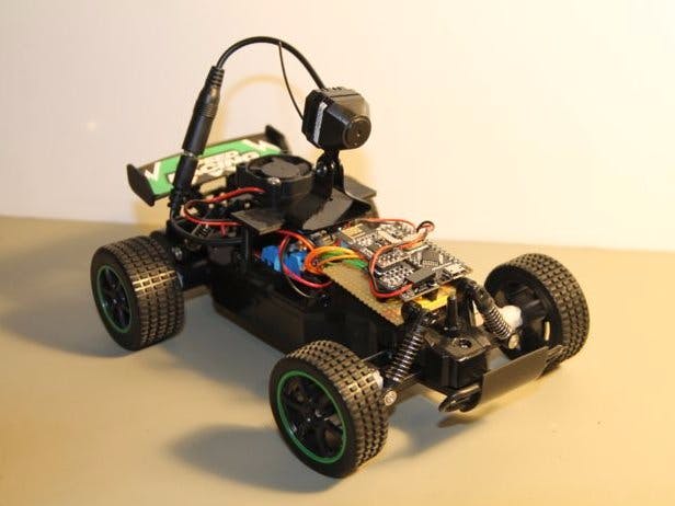
CThis project had been in my drawer for some time and since the Maker Fair's coming to town, this was a good time to make it.
A long time ago, there was a game called "Micro Machines" for Sega Mega Drive (Genesis) that I spent hours playing. Basically this was a racing game with small cars where the race track was parts of daily life objects. I found that there is a new version of this old classic.
On the original version, the game had top view of the track and cars, but I wanted to have the first person view in a head display. The camera would move according to the movement of the head of the player.
The controller should be a racing wheel. Unfortunately, this was not possible and, in the end, this was what I got.
Due to several factors, I did not implemented the head display and servo-controlled camera but the car is controller by the racing wheel, I have a wireless camera and everything works. The problem is the range. I can only control and see camera feed if every transmitter and receiver units are in line of sight.
In any case there are very interesting aspects of this project worth sharing.
ComponentsRC Car
I just selected the cheapest that I could find in a 1:20 scale.
Wireless Camera
I had several choices here but I probably went with the worst one. If you are planning on doing something like this, DO NOT use these type of cameras.
Microcontroller
DFRobot Dreamer Nano V4.1, the 2.54mm pinout is essencial for this project. Check DFRobot wiki page for more info regarding this microcontroller.
Computer Racing Wheel
Today it is very easy to find old racing controllers almost for free. This one I got for free in the local internet market.
It comes with the old 15 pins game port, that connects with the sound card of the computer.
Motor Controller
The choice was the L298N with a capability of 2A and with a max of 46V in the input which serves perfectly for this project.
RF transceiver
For the wireless communication between the racing wheel and car, I went with the nRF24L01+ RF transceiver.
I already had some here, and they are easy to use.
Battery
A 7.4V 800mA LiPo battery provides the power to the RC car, microcontroller, RF transceiver, and wireless camera
Miscellaneous
- 4x - 10K Resistor
- 4x - 100K Resistor
- Perfboard (a usual in my projects)
- 9V battery plug
- some wires
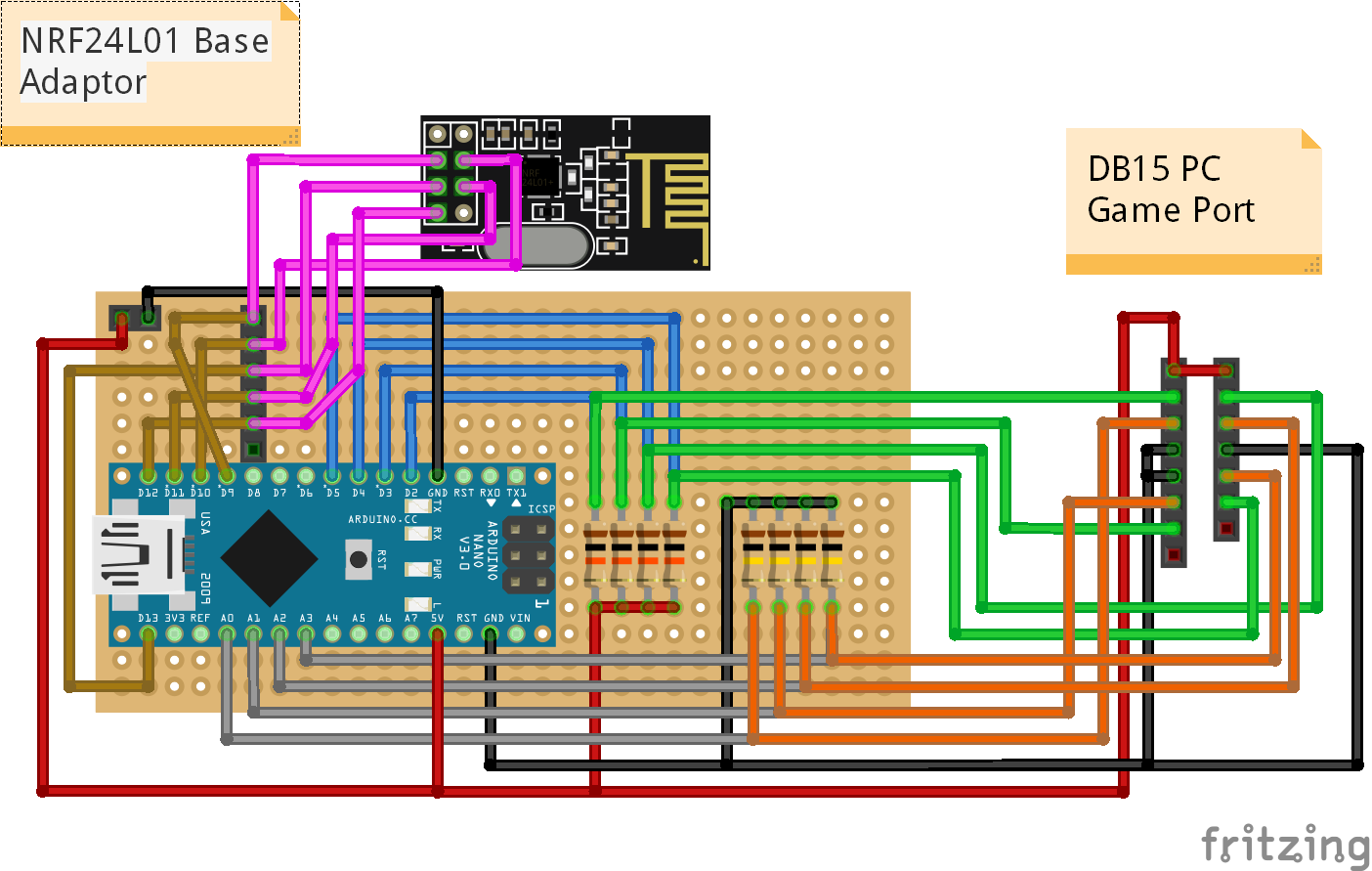
Computar Racing Wheel Transmitter
The game port pin out can be find here: https://en.wikipedia.org/wiki/Game_por
I also found a very nice site with a schematic for the connection to the Arduino: http://www.built-to-spec.com/blog/2009/09/10/using-a-pc-joystick-with-the-arduino/
The circuit is built on the prefboard according to the schematic that I've added.
For the NRF24L01+ connection I'm using the base adapter that bring a 3.3V voltage regulator plus additional capacitors for increasing the line stabilization.
If you want just to use the NRF24L01+, the power line need to come from the +3.3V from the Arduino.
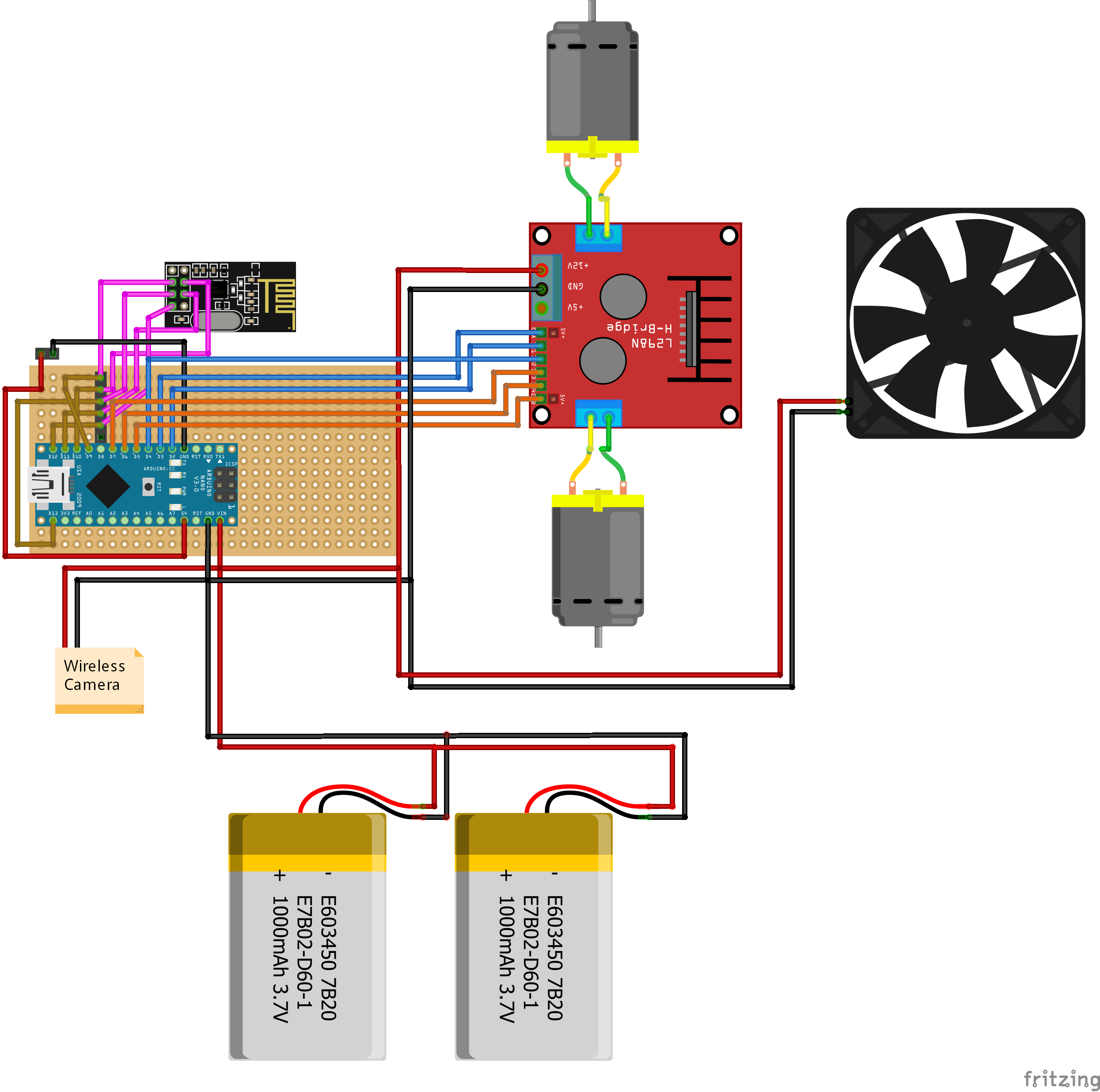
RC Car Receiver
- For the car, I also use the NRF24L01+ base adapter - again, this is optional.
- The L298n connects to pins D2 to D7.
- The power for a wireless camera also comes from the battery pack.
- After some tests, I used the rule of thumb for the heat sink and decided to use a fan.
For the code to run, you will need to install the RF24 library.
You can download it here: https://github.com/nRF24/RF24.
Pins D9 and D10 are used also for this library, so do not forget to change them if you want to use other ones.
RF24 radio(9, 10); //Set up nRF24L01+ radio on SPI bus plus pins 9 and 10
Then declare the pins for the controller in the Car_TX code.
//Declare the pins for the racing wheel
const int wheel_direction = A0;
const int button_1A = 2;
const int Button_2A = 4;
const int button_1B = 3;
const int button_2B = 5;
And the pins for the motor controller drive
//Define Pins for Motor Drive
//Motor Speed
int enable_A = 3;
int in1Pin = 2;
int in2Pin = 4;
//Motor Direction
int enable_B = 5;
int in3Pin = 6;
int in4Pin = 7;
The wireless camera set consists of a wireless camera and a receiver capable of outputting a composed video signal. The receiver is then connected to a converter that allows a connection to VGA monitors.
Functional TestConclusionAfter finishing everything and assembling it, the result was not the one expected. The range of everything was about 2m indoors! Probably because this was done with a budget of around 50€!!
This one needs a complete rethinking on the components selected. I will probably use, in the future, the same cameras and transmitters used in the drones with FPV. Today it is already possible to get some equipment without breaking the bank.
Not everything was bad. During the tests, it was very fun to drive the car with the racing controller. I will probably build a new version using small RC car but with a racing wheel controller.
Feel free to comment or send me a message if you found any mistakes, or if you have any suggestions/improvements or questions.
Like it. Subscribe. Make it.

Comments