



Hardware components | ||||||
 |
| × | 1 | |||
| × | 1 | ||||
| × | 1 | ||||
| × | 1 | ||||
| × | 1 | ||||
| × | 1 | ||||
| × | 1 | ||||
| × | 1 | ||||
| × | 1 | ||||
| × | 1 | ||||
| × | 1 | ||||
| × | 1 | ||||
Software apps and online services | ||||||
| ||||||
 |
| |||||
 |
| |||||
Hand tools and fabrication machines | ||||||
 |
| |||||
 |
| |||||
 |
| |||||
 |
| |||||
 |
| |||||
Power wastage in large covered spaces such as corridors, auditoriums, waiting halls, office floors, and public buildings is a significant challenge. Traditional lighting and ventilation systems operate continuously regardless of occupancy, daylight availability, or environmental conditions, leading to unnecessary energy consumption.
To address this issue, I Have developed an AI-powered smart energy management for intelligent and sustainable spaces. that intelligently manages lighting and fan operations based on real-time conditions.
The system uses cameras installed in the monitored area to stream live video to a microcontroller-based processing unit. Using Artificial Intelligence and computer vision, the system detects human presence and identifies the position of occupants within the space.
In addition, the solution integrates:
- LDR sensors to measure ambient light intensity.
- Temperature sensors to monitor environmental conditions.
- Smart controllers to regulate lights and fan speeds automatically.
Based on occupancy, temperature, and natural light levels, the system:
- Switches lights ON only where people are present.
- Adjusts light brightness according to available daylight.
- Controls fan operation based on occupancy and temperature.
- Dynamically regulates fan speed to maintain comfort while minimizing energy usage.
- Turns OFF unused electrical appliances in vacant zones.
To further enhance efficiency, the system is connected to a cloud platform. The microcontroller continuously uploads power consumption data to the cloud, enabling real-time monitoring and analysis.
The cloud dashboard provides:
- Live energy consumption monitoring.
- Daily, weekly, and monthly power usage reports.
- Date-wise and time-wise energy analytics.
- Graphical visualization of energy consumption trends.
- Performance insights and energy-saving statistics.
- Remote access for facility managers and administrators.
Reducing energy waste is essential because it benefits the environment, economy, and society.
🌍 Protects the Environment
Most electricity is still generated from fossil fuels. Wasting energy increases carbon emissions, contributing to climate change, air pollution, and environmental degradation.
💰 Reduces Energy Costs
Using only the required amount of electricity lowers electricity bills for homes, businesses, schools, and public institutions, saving significant money over time.
⚡ Conserves Natural Resources
Energy production consumes valuable natural resources such as coal, oil, natural gas, and water. Reducing waste helps preserve these resources for future generations.
🔋 Improves Energy Efficiency
Efficient energy use ensures that available power is utilized effectively, reducing unnecessary demand on the electrical grid.
🏙️ Supports Sustainable Smart Cities
Smart energy management systems help create sustainable buildings and cities by optimizing energy consumption through automation and intelligent control.
🌱 Reduces Carbon Footprint
Every unit of electricity saved reduces greenhouse gas emissions, helping organizations and communities meet sustainability goals.
🚀 Enables a Smarter Future
Technologies such as AI, IoT, sensors, and cloud analytics can automatically manage energy usage, making buildings more intelligent, comfortable, and efficient.
EnerVision's Impact
EnerVision reduces energy waste by ensuring that lights and fans operate only when and where they are needed, using AI-based occupancy detection, environmental sensing, and cloud-based analytics.STEP BY STEP DEVELOPMENT FOR PERSON DETECTION MODULE:
"Rather than relying solely on existing pretrained solutions, I developed and publicly deployed my own Edge Impulse-based Person Detection module, which forms the AI backbone of EnerVision's occupancy-driven energy optimization system."
As part of the EnerVision: AI-Powered Smart Energy Management for Intelligent and Sustainable Spaces project, I developed the Person Detection Module responsible for real-time occupancy detection in covered spaces.
Although pretrained person-detection models are available in App Lab, I independently designed and implemented a customized detection solution using Edge Impulse. The model, named "Person Detection", was trained, deployed, and published as a public Edge Impulse project.
Development Process
- Created a new Edge Impulse project named Person Detection.
- Collected and prepared image samples containing people in corridor and indoor environments.
- Applied image preprocessing and feature extraction pipelines.
- Trained and optimized the model for person detection using Edge Impulse's machine learning workflow.
- Validated the model and evaluated inference performance.
- Deployed the trained model for integration with the EnerVision automation system.
Contribution to EnerVision
The Person Detection module serves as the core intelligence of EnerVision by:
- Detecting human presence in real time.
- Identifying occupied zones within large covered spaces.
- Triggering intelligent control of lights and fans only where required.
- Providing occupancy information for cloud-based monitoring and analytics.
- Enabling significant energy savings through AI-driven automation.
This contribution demonstrates the practical application of computer vision, embedded machine learning, and IoT integration for creating intelligent and sustainable energy management systems.
Step 1: Project CreationA new Edge Impulse project named Person Detection was created.
- Project Type: Object Detection
- Visibility: Public
- Target Device: Arduino UNO (deployment target)
The public project can be viewed and reused by the community, contributing to open AI development.
Step 2: Dataset Collection
Dataset Statistics:
- Total Images: 364
- Training Images: 294
- Test Images: 70
- Train-Test Split: 81% : 19%
Images containing people in different positions and environments were collected and labeled.
Purpose:To improve the model's ability to detect people under varying conditions, lighting environments, and viewing angles.
Step 3: Automatic Bounding Box LabelingInstead of manually drawing every bounding box, Edge Impulse's pretrained object detection blocks were utilized:
- OWL-ViT Zero-Shot Object Detector
- GPT-4o Bounding Box Re-labeling
- Bounding Box Validation Tools
These tools automatically identified people and generated bounding boxes around them, significantly reducing annotation time.
Step 4: Impulse DesignThe impulse pipeline consists of:
Input Block
- Image Size: 320 × 320
- Color Mode: RGB
- Resize Mode: Squash
Processing Block
- Image preprocessing and feature extraction
Learning Block
- Object Detection (Images)
Output:
- 1 Class → Person
The system learns to locate people and predict their coordinates inside an image.
Step 5: Feature GenerationRaw images were converted into numerical features.
Operations performed:
- Image normalization
- RGB preprocessing
- Feature extraction
These features become the input for the neural network.
Step 6: Model TrainingTraining Configuration:
- Training Processor: GPU
- Epochs/Cycles: 10
- Learning Rate: 0.001
- Model Size: Small (≈6.9 MB)
- Pretrained Weights: Enabled
Neural Network
YOLO-Pro Architecture
Using pretrained weights allows transfer learning, enabling the model to learn faster and achieve better performance with fewer training samples.
Step 7: Training PerformanceValidation Performance
mAP@50 = 1.00 (100%)
Precision Score ≈ 95.45%
This indicates that the model achieved excellent detection performance on the validation dataset.
Step 8: Model TestingTesting Results:
mAP@50 ≈ 0.76
Precision ≈ 68.75%
Accuracy ≈ 74.29%
The feature explorer showed good separation between correctly detected and incorrectly detected samples, demonstrating that the model generalizes reasonably well to unseen data.
Step 9: Edge DeploymentDeployment Options:
Quantized (int8)
- RAM: ~1.8 MB
- Flash: ~7.1 MB
- Inference Time: ~1989 ms
Float32
- RAM: ~5.3 MB
- Flash: ~27.5 MB
The quantized model significantly reduces memory requirements and is suitable for deployment on resource-constrained edge devices.
Integration with EnerVision
The Person Detection module serves as the intelligence layer of EnerVision.
Workflow:
Final Outcome: Real-Time Person Detection Using Edge Impulse and Person Detection
Integration of Edge Impulse Model into Arduino App Lab
Step 1: Sign in to Arduino App Lab
The process begins by opening Arduino App Lab and navigating to the Account section. Signing in with an Arduino account unlocks advanced features such as:
- AI model training with Edge Impulse
- Arduino Cloud integration
- Project publishing and sharing
Step 2: Authenticate Using Arduino Credentials
The user signs in using an Arduino account through Google, GitHub, Apple, or email credentials. Authentication grants access to AI development and Edge Impulse integration services.
Step 3: Grant App Lab Access
After successful authentication, permission is granted for Arduino App Lab to access the user's Arduino account and associated AI development resources.
Step 4: Verify Account Information
The account dashboard displays the user's profile information, confirming successful login and enabling cloud-based AI services within App Lab.
Step 5: Add the Custom AI Model
Navigate to:
Bricks → Video Object Detection → AI Models
The custom Edge Impulse model Person Detection appears alongside the pretrained models and is marked as Installed.
"I authenticated Arduino App Lab using my Arduino account and integrated my publicly published Edge Impulse model, Person Detection, into the Video Object Detection Brick. This enabled real-time person detection on the Arduino UNO Q platform and formed the AI foundation of EnerVision's occupancy-based smart energy management system."
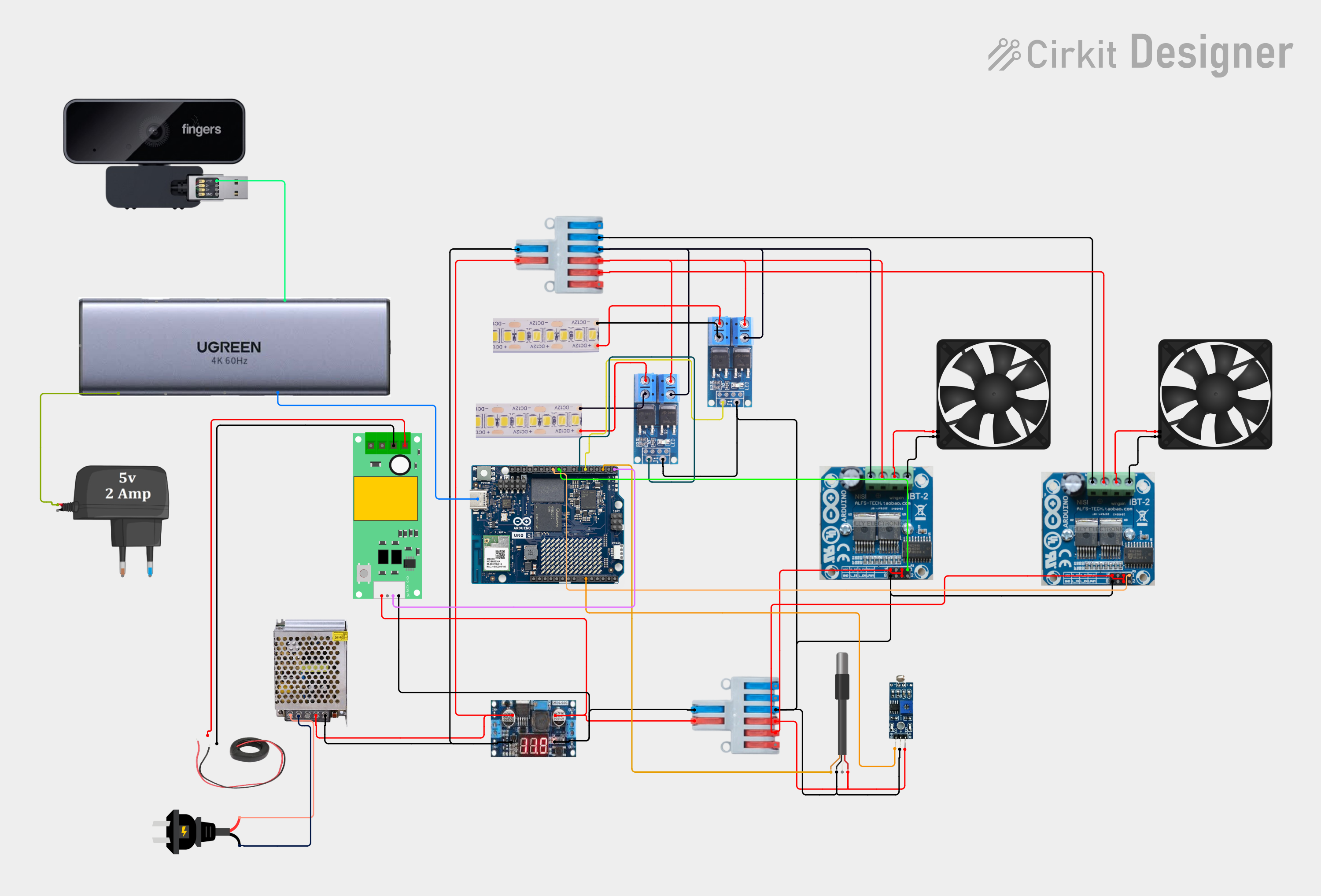
Hardware Description:Actual hardware components used in the EnerVision prototype, including the Arduino UNO Q, camera module, LED lighting modules with mosfet drivers, DC 12V fans,, Load sensor, LDR sensor, temperature sensor, motor H-Bridge drivers, USB-C hub, and supporting modules for AI-driven occupancy detection, intelligent automation, and cloud-based energy monitoring.
The Arduino UNO Q board serves as the central controller of EnerVision, integrating the Edge Impulse-based Person Detection model, processing sensor data, executing occupancy-based decision logic, controlling lights and fans with intensity, and enabling cloud connectivity for real-time energy monitoring and analytics.
The USB-C hub provides power distribution and peripheral connectivity for the EnerVision prototype, enabling the integration of cameras and power supply.
The USB camera module captures real-time video streams of the monitored area and provides input to the Edge Impulse-based Person Detection model for occupancy detection and intelligent energy automation in the EnerVision system.
The LDR sensor, DS18B20 temperature sensor, and current sensor module collectively monitor ambient light intensity, environmental temperature, and electrical power consumption, providing real-time inputs for intelligent lighting control, fan speed regulation, and cloud-based energy analytics in the EnerVision system.
The MOSFET switching modules, 12 V LED lighting modules, BTS7960 H-bridge motor drivers, and DC cooling fans collectively form the power control subsystem of EnerVision. The MOSFET modules provide ON/OFF control of LED lighting, while the BTS7960 H-bridge drivers regulate fan operation and speed. These components enable intelligent occupancy-based lighting and adaptive cooling control for energy-efficient automation.
The LM2596 DC-DC buck converter provides a regulated 5 V power supply to sensors and actuators in the EnerVision prototype. A separate power module is used instead of the Arduino UNO Q onboard 5 V regulator to prevent excessive current loading, improve system stability, and protect the microcontroller from potential damage caused by high-current peripherals.
The prototype utilizes a dedicated 12 V DC adapter and power distribution board to supply electrical power to the LED lighting modules and DC fans. A separate actuator power supply is employed to isolate high-current loads from the Arduino UNO Q, ensuring reliable operation, preventing voltage drops, and protecting the microcontroller during real-time energy automation.
Project Architecture :The block diagram illustrates the complete architecture of the EnerVision: AI-Powered Smart Energy Management System, which combines Artificial Intelligence (AI), Internet of Things (IoT), environmental sensing, and cloud analytics to optimize energy consumption in large indoor spaces such as corridors, halls, offices, and public infrastructures.
1. Video Input and Person Detection
A USB camera continuously captures the live video stream of the monitored area. The video is processed using the Person Detection model, developed with Edge Impulse and YOLO-Pro. The AI model detects the presence of people and determines whether they are located in the left or right region of the camera frame.
2. Environmental Sensing
The system uses two environmental sensors:
- LDR Sensor: Measures ambient light intensity and determines the availability of natural daylight.
- DS18B20 Temperature Sensor: Measures the surrounding temperature to regulate cooling requirements.
These sensors provide real-time environmental information to the control system.
3. Arduino UNO Q Decision Engine
The Arduino UNO Q acts as the central decision-making unit of the system. It receives:
- Occupancy information from the AI model
- Person position (left or right zone)
- Ambient light intensity
- Temperature measurements
Based on these inputs, the controller executes intelligent energy management algorithms.
4. Zone-Based Energy Control Algorithm
The control algorithm performs occupancy-driven energy optimization. Depending on the detected person's position:
- Only the required left or right lighting zone is activated.
- Fan operation and speed are adjusted according to occupancy and temperature conditions.
- Lighting intensity can be reduced when sufficient natural daylight is available.
This zone-wise control minimizes unnecessary power consumption.
5. Lighting and Fan Control
The system uses dedicated driver modules:
- MOSFET Drivers: Control the ON/OFF operation of LED lighting modules.
- BTS7960 H-Bridge Drivers: Control the operation and speed of DC fans.
The drivers operate the corresponding left and right zone actuators independently.
6. Power Monitoring
A current /loadsensor module continuously measures the electrical current consumed by the lighting and fan loads. The measured values are used to estimate power consumption and evaluate energy savings.
7. Power Supply Architecture
To ensure reliable operation:
- A 12 V DC power supply powers the LED lights and DC fans.
- A 5 V DC-DC buck converter provides regulated power to sensors and control circuits.
Using dedicated power supplies prevents overloading and protects the Arduino UNO Q from high-current actuator loads.
8. Cloud Monitoring and Analytics
The energy consumption data is transmitted to a cloud platform, where administrators can:
- Monitor real-time power consumption
- View historical energy graphs
- Analyze date-wise and time-wise reports
- Evaluate system performance and energy savings
Working Principle
The EnerVision system continuously detects human occupancy, identifies the person's position within the monitored area, senses environmental conditions, and intelligently controls only the necessary lights and fans. By integrating AI, IoT, environmental sensing, and cloud analytics, the system significantly reduces energy wastage while maintaining occupant comfort and enabling data-driven energy management.
First level of hardware integration and output validating:Step 1: Prepare Sensors and Actuators
- Identify all sensors and actuators required for the project.
- Determine the operating voltage ( 5 V, or 12 V) and communication interface (GPIO, UART, PWM, One wire, Analog) for each device.
- Verify compatibility with the Arduino UNO Q board.
- Test each sensor and actuator individually using simple test programs to ensure proper functionality before integration.
Step 2: Design and Assemble Breakout Boards
Design custom breakout boards for securely mounting sensors, actuators, and interface modules.
- Include screw terminals or JST connectors for reliable field wiring.
- Route power and signal traces carefully to minimize electrical noise.
- Clearly label all power, ground, GPIO, and communication pins for easy installation and maintenance.
Step 3: Firmly Mount Hardware Components
Mount the Arduino UNO Q, breakout boards, sensors, actuators, voltage regulators, and communication modules inside the prototype enclosure.
- Secure components using spacers, screws, or mounting brackets.
- Organize wiring using cable ties or cable ducts to prevent loose connections and improve maintainability.
Step 4: Configure Voltage Regulators
Adjust the DC-DC buck/boost regulators to provide the required output voltages (5 V, and/or 12 V).
- Measure the regulator outputs with a digital multimeter.
- Verify stable voltage levels before connecting them to the Arduino UNO Q and peripheral devices.
Step 5: Perform Power Distribution
Connect the regulated power supplies to the Arduino UNO Q, sensors, actuators, camera module, and communication peripherals.
- Ensure a common ground connection across all hardware.
- Incorporate reverse-polarity protection, fuses, or overcurrent protection where necessary.
Step 6: Create an Arduino Cloud Account
- Register an account on Arduino Cloud.
- Create a new cloud workspace and initialize a new project.
- Configure the project settings for cloud connectivity.
The first step in configuring the Arduino IoT Cloud is to create a new Thing, which acts as a virtual representation of the physical IoT device. A Thing stores all the cloud variables, device information, metadata, and program sketch associated with the project. After logging into the Arduino IoT Cloud dashboard, the user selects Things from the IoT Builder menu and clicks Create Thing. This establishes the cloud environment where sensor readings and control commands will be exchanged between the hardware and the cloud platform
Once the Thing is created, cloud variables are added to represent the data exchanged between the ESP32 and Arduino Cloud. In this project, variables such as voltage, current, power, person_count_total, and last_detection_time are created. These variables automatically synchronize real-time values between the IoT device and the cloud dashboard, allowing continuous monitoring of electrical parameters and AI-based person detection results.
The next step is to register the hardware device with Arduino Cloud. By selecting Devices and clicking Add Device, the platform begins the device registration process. This allows the selected microcontroller board to communicate securely with the cloud using encrypted credentials and enables remote monitoring and control.
Since the project uses an Arduino UNO Q, the manual setup option is selected. Arduino Cloud provides several configuration methods, including automatic setup and manual setup. The manual configuration allows developers to register compatible hardware and later program it using Arduino App Lab or Arduino IDE. This method is suitable for advanced IoT applications requiring custom firmware.
During device registration, Arduino Cloud provides instructions for configuring the Arduino UNO Q. The setup process involves creating the device, obtaining unique authentication credentials, and linking the board with Arduino Cloud. Once configured, the Arduino UNO Q becomes ready to communicate securely with the cloud platform and exchange IoT data.
In the final configuration step, Arduino Cloud generates a unique Device ID and Secret Key for the registered Arduino UNO Q. These credentials authenticate the device whenever it connects to the cloud. The Secret Key is displayed only once during setup and must be stored securely, as it cannot be recovered later. These credentials are later entered into the Arduino App Lab or firmware to establish secure cloud communication.
After configuring the Thing and cloud variables, a dashboard is created for real-time visualization of sensor data. The dashboard contains gauge widgets for Voltage, Current, Power, and Person Count, along with historical trend graphs. The dashboard continuously displays live data received from the ESP32, enabling users to monitor electrical energy consumption and occupancy information remotely through any web browser.
Step 7: Register the Arduino UNO Q Device
- Add the Arduino UNO Q board as a new device in Arduino Cloud.
- Generate and configure the Device ID and Cloud ID.
- Verify successful cloud registration and device connectivity.
Step 8: Configure Arduino Cloud Bricks
- Add the Arduino Cloud Brick to the application workflow.
- Configure cloud variables for sensor data, AI detection status, and actuator control.
- Link the cloud services using the Device ID and Cloud ID.
After generating the Device ID and Secret Key in Arduino IoT Cloud, these credentials must be entered into the Arduino App Lab to establish a secure connection between the Arduino UNO Q and the Arduino Cloud. Under the Arduino Cloud configuration settings, the Arduino Cloud Device ID and Arduino Cloud Secret fields are populated with the credentials generated during device registration. These authentication keys uniquely identify the device and ensure secure communication with the cloud platform. Once the credentials are entered correctly, the application can securely publish sensor data and receive cloud commands, enabling seamless real-time IoT monitoring and remote device management.
Step 9: Integrate the Person Detection Module
- Import the exported Edge Impulse model into the Arduino UNO Q project.
- Configure the AI inference pipeline.
- Add the Person Detection module to the application workflow and verify its functionality.
Step 10: Configure the Video Object Detection Brick
- Add the Video Object Detection Brick within the Arduino application.
- Integrate the exported YOLO-Pro Person Detection model with the video processing pipeline.
- Validate real-time object detection performance.
Step 11: Connect AI Output with Arduino Cloud
- Send person detection results and confidence scores to Arduino Cloud.
- Update cloud dashboards with real-time AI inference results.
- Enable cloud-based visualization and monitoring of detection events.
Step 12: Verify End-to-End System Operation
- Test all sensors, actuators, AI inference, cloud communication, and hardware interfaces.
- Validate real-time person detection, cloud synchronization, and actuator responses.
- Perform system-level testing to ensure reliable operation as a complete AI-enabled embedded system based on the Arduino UNO Q.
The goal is to present the problem, solution idea, and a working proof-of-concept within a short time, current progress of implementation.
Code ExplanationThe Python program implements an AI-based Dual-Side Person Detection and Environmental Control System using Arduino App Lab. It integrates Video Object Detection, Web UI, Arduino Bridge, and Arduino Cloud to detect people, control LEDs and fans, monitor environmental parameters, and upload real-time data to the cloud. The following sections explain the code in detail.
1. Importing Libraries
The program begins by importing the required libraries.
from arduino.app_utils import App, Bridge
from arduino.app_bricks.web_ui import WebUI
from arduino.app_bricks.video_objectdetection import VideoObjectDetection
from arduino.app_bricks.arduino_cloud import ArduinoCloud
from datetime import datetime, UTC
import threading
import time
from arduino.app_utils import App, Bridge
from arduino.app_bricks.web_ui import WebUI
from arduino.app_bricks.video_objectdetection import VideoObjectDetection
from arduino.app_bricks.arduino_cloud import ArduinoCloud
from datetime import datetime, UTC
import threading
import time- Bridge establishes communication between Python and the Arduino board.
- WebUI creates a real-time dashboard for displaying sensor readings and detection status.
- VideoObjectDetection provides AI-based person detection using the camera.
- ArduinoCloud synchronizes all variables with Arduino Cloud for remote monitoring.
- threading enables multiple tasks to run simultaneously.
- datetime records timestamps of detections.
- time is used for delays and timer-based operations.
2. Initializing Objects
bridge = Bridge()
iot_cloud = ArduinoCloud()
ui = WebUI()
detection_stream = VideoObjectDetection(confidence=0.5)
bridge = Bridge()
iot_cloud = ArduinoCloud()
ui = WebUI()
detection_stream = VideoObjectDetection(confidence=0.5)
The program initializes four main objects.
- Bridge communicates with Arduino functions.
- ArduinoCloud uploads and receives cloud data.
- WebUI manages the browser interface.
- VideoObjectDetection starts the AI model with a confidence threshold of 50%.
3. Global Variables
The program declares several global variables.
Examples include
current_person_left
current_person_right
current_temperature
current_voltage
current_power
current_energy
current_person_left
current_person_right
current_temperature
current_voltage
current_power
current_energy
These variables temporarily store:
- Person detection status
- Number of detected persons
- Temperature
- Fan speed
- LED intensity
- LDR value
- Voltage
- Current
- Power
- Energy
- Frequency
- Power Factor
The variables are continuously updated throughout program execution.
4. Arduino Cloud Registration
The following statements register variables with Arduino Cloud.
iot_cloud.register(...)
iot_cloud.register(...)
Each sensor and AI variable is registered so that it can be monitored remotely.
Examples include:
- Person Left
- Person Right
- Person Count
- Temperature
- Fan Speed
- Voltage
- Current
- Power
- Energy
- Frequency
- Power Factor
Whenever these variables change, the cloud is automatically updated.
5. Callback Functions
Each cloud variable has a callback function.
Example
def cloud_temperature_callback(client, value):
def cloud_temperature_callback(client, value):
Whenever Arduino Cloud receives a new value, the callback function executes automatically.
For example,
Temperature updated to 28°C
Temperature updated to 28°C
is printed on the terminal.
This confirms successful cloud synchronization.
6. Updating Arduino Cloud
update_arduino_cloud()
update_arduino_cloud()
This function uploads all current values to Arduino Cloud.
It updates:
- Person detection
- Temperature
- Fan speed
- LED intensity
- LDR value
- Voltage
- Current
- Power
- Energy
- Frequency
- Power Factor
This keeps the cloud dashboard synchronized with the local system.
7. Determining Person Position
get_person_position()
get_person_position()
The AI model returns a bounding box around each detected person.
The function calculates the horizontal center of the bounding box.
If
Center X ≤ 50%
Center X ≤ 50%
the person is classified as LEFT.
Otherwise
Center X > 50%
Center X > 50%
the person is classified as RIGHT.
This allows independent control of left and right lighting and fans.
8. Controlling Arduino Outputs
update_arduino_person_detection()
update_arduino_person_detection()
This function sends commands from Python to Arduino.
For example,
bridge.call("set_person_left",1)
bridge.call("set_person_left",1)
turns ON the left LED and fan.
bridge.call("set_person_right",1)
bridge.call("set_person_right",1)
turns ON the right LED and fan.
If no person is detected, both outputs are switched OFF.
9. Detection Status
get_detection_status()
get_detection_status()This function creates a dictionary containing
- Left detection status
- Right detection status
Left count
- Right count
- Total count
- Last detection time
The dictionary is sent to the Web UI so that users can monitor occupancy in real time.
10. Processing AI Detection
handle_detection()
handle_detection()
This is the core function of the application.
Whenever the camera detects objects, the function:
- Reads all detected persons.
- Extracts the confidence score.
- Determines whether each person is on the left or right side.
- Counts people on each side.
- Updates global variables.
- Sends commands to Arduino.
- Updates Arduino Cloud.
- Sends detection information to the Web UI.
This function links the AI detection system with the hardware control system.
11. Reading Sensor Data
read_arduino_sensors()
read_arduino_sensors()
The function reads environmental and electrical parameters from the Arduino.
It collects data from:
- DS18B20 Temperature Sensor
- LDR
- LED PWM output
- Fan speed
- PZEM Voltage
- PZEM Current
- PZEM Power
- PZEM Energy
- PZEM Frequency
- PZEM Power Factor
All readings are stored in global variables.
12. Automatic Light and Fan Control
The Arduino automatically adjusts the outputs based on sensor readings.
Light Control
The LDR measures ambient light intensity.
- Bright surroundings → LED brightness decreases.
- Dark surroundings → LED brightness increases.
Fan Control
The DS18B20 measures room temperature.
- Low temperature → Fan remains OFF or runs at low speed.
- Medium temperature → Fan speed increases gradually.
- High temperature → Fan runs at maximum speed.
The current LED intensity and fan speed are sent to the Web UI and Arduino Cloud for monitoring.
13. Periodic Sensor Updates
update_sensors_periodically()
update_sensors_periodically()
A background thread runs every 2 seconds.
During each cycle it:
- Reads all sensors from Arduino.
- Updates the Web UI.
- Uploads the latest values to Arduino Cloud.
- Displays system status in the terminal.
This ensures that the dashboard and cloud always show the latest information.
14. Automatic Reset
check_no_person_reset()
check_no_person_reset()
The application continuously checks whether a person has been absent for 10 seconds.
If no occupancy is detected:- Left LED is turned OFF.
- Right LED is turned OFF.
- Both fans are turned OFF.
- Person counters are reset.
- Arduino Cloud is updated.
- Web UI displays the reset status.
This feature improves energy efficiency by ensuring devices are not left running unnecessarily.
15. Web UI Event Handlers
The Web UI provides interactive controls.
Override Detection Threshold
Allows the user to change the AI confidence threshold.
Get Initial State
When a client opens the dashboard, the application immediately sends:
- Detection status
- Temperature
- Fan speed
- LED intensity
- LDR value
- Voltage
- Current
- Power
- Energy
Reset Arduino
Provides a button to turn OFF all outputs directly from the Web UI.
16. Multithreading
The application creates two background threads.
Sensor Thread
Runs every 2 seconds to:
- Read sensors.
- Update the Web UI.
- Synchronize Arduino Cloud.
Monitor Thread
Continuously checks for inactivity and resets the system after 10 seconds without person detection.
Running these tasks in separate threads ensures that AI detection, sensor monitoring, and cloud communication operate simultaneously without interrupting one another.
17. Starting the Application
The application starts with:
detection_stream.on_detect_all(handle_detection)
App.run()
detection_stream.on_detect_all(handle_detection)
App.run()
These commands:
- Register the AI detection callback.
- Start the camera.
- Enable Arduino communication.
- Launch the Web UI server.
- Activate Arduino Cloud synchronization.
- Begin continuous monitoring and automatic environmental control.
- The camera captures live video frames.
- The Video Object Detection brick detects people in each frame.
- The application determines whether each detected person is on the left or right side.
- Detection information is sent to the Arduino through the Bridge.
- The Arduino controls the corresponding LEDs and fans based on occupancy.
- The Arduino reads temperature, ambient light, and PZEM electrical parameters.
- LED brightness is automatically adjusted according to ambient light, and fan speed is automatically adjusted according to room temperature.
- All occupancy, environmental, and electrical data are displayed on the Web UI and synchronized with Arduino Cloud.
- If no person is detected for 10 seconds, the system automatically turns OFF all outputs and resets the occupancy status, improving energy efficiency.
The authors sincerely express their gratitude to the creators and contributors of the open-source 3D design community for making high-quality printable models freely available. The 3D-printed miniature furniture, human figures, doors, windows, and other decorative components used in the EnerVision prototype were sourced from publicly available open 3D model repositories. These models were utilized solely to enhance the visual presentation and realism of the prototype and were not claimed as original design work. The authors acknowledge and appreciate the efforts of the designers and the following platforms for providing valuable resources:
- Thingiverse – https://www.thingiverse.com
- Printables – https://www.printables.com
- MakerWorld – https://makerworld.com


Comments