

Hardware components | ||||||
| × | 1 | ||||
| × | 4 | ||||
_ztBMuBhMHo.jpg?auto=compress%2Cformat&w=48&h=48&fit=fill&bg=ffffff) |
| × | 1 | |||
| × | 8 | ||||
| × | 2 | ||||
| × | 1 | ||||
| × | 4 | ||||
| × | 1 | ||||
| × | 1 | ||||
At BBRI's "Structures & Construction System" lab, the acquisition of measurement data is usually performed using classical DAQ system (from Fluke, National Instrument or other commercial solution). Few years ago, we needed to deal with the unavailability of our well-known solutions for a project for which long-term measurement (order of 1 year) were required. We then decided to develop an in-house acquisition system based on the well-documented Arduino platform for the measurement of at least 24 entries. The very first version were realized using breadboards. This was easy to modify but the connections were definitely not reliable nor traceable (see figure herein-below :-o!).
After validating that the global process that met our expectations, in terms of:
- Robustness,
- Accuracy,
- Ease of use.
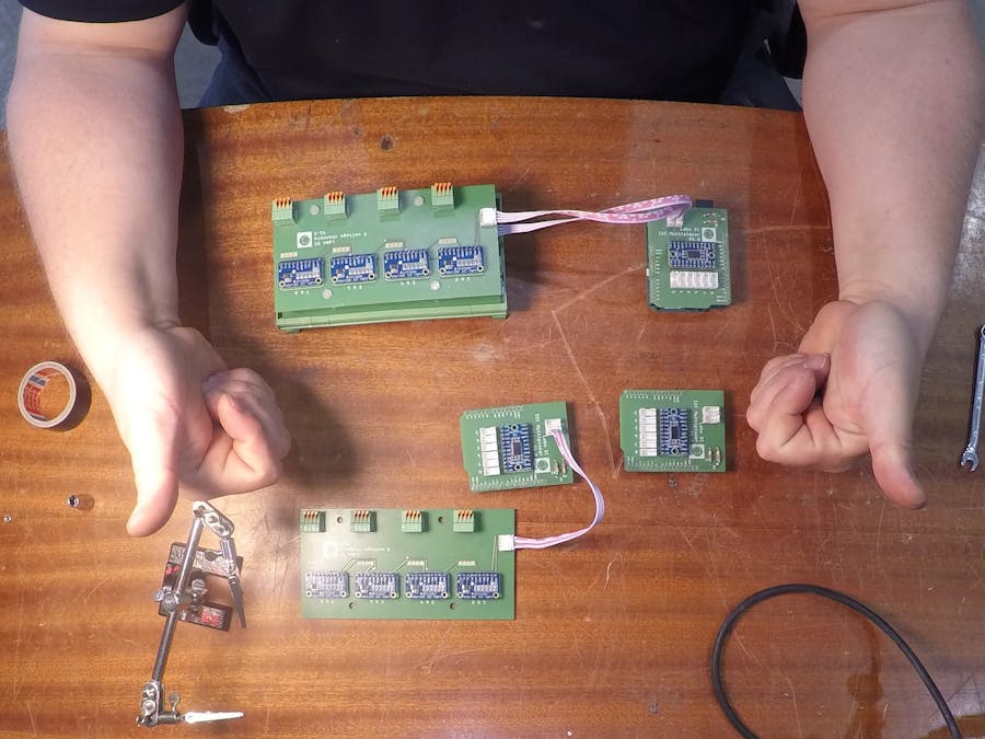
We then made a more professional packaging (see figure below). The breadboard is only in order to perform divider bridges.
As the community made this project so easy to set up, we here share all you need to exploit what we developed (i.e. hardware choices, Arduino code, PCB's Fritzing files and Windows GUI source code) ;-)
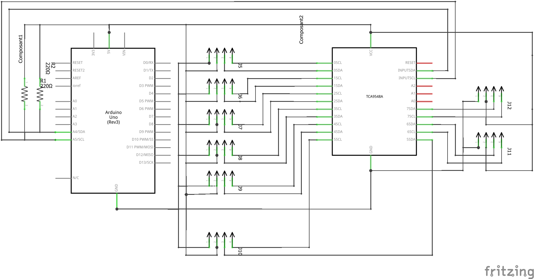
The global idea is the following. An Arduino Uno is connected to a multiplexer, enabling to extend to number of I2C addresses. On each multiplexer output (eight in total), four ADS1115 are connected. The measurements are transmitted through RS232 port to a Windows PC. Finally a Windows GUI (here called ArDAQ) enables to control the entire measurement process:
- Start/stop measurement
- Recording
- Calibration
- Live monitoring
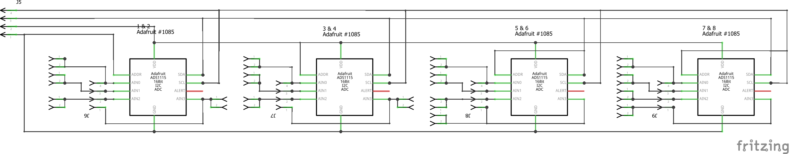
The solution is split in two parts. First a multiplexer PCB, staked on an Arduino UNO, is dedicated to the connection of a user-defined number of acquisition PCB (maximum 8, the number of outputs of the multiplexer). Given that the measurements is performed in differential mode (if required that could be changed in the Arduino's sketch) and given that there are four ADS115 per acquisition PCB, we thus have 8 entries (measurements) per acquisition PCB. The maximal number of acquisition PCB is 8 (the number of multiplexer output).
Soldering and assembling of the PCB are illustrated in the following video.
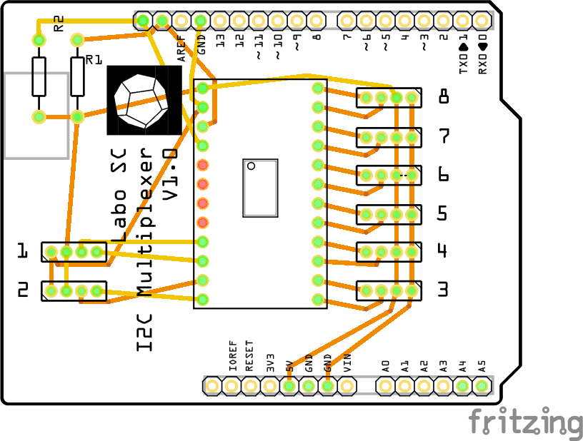
1. The multiplexer PCB basically contains a mutiplexer (I2C TCA9548A), designed to be easily staked on the UNO. Two optional 2k pull-up resistors can be added in the SDA & SCL wires. In case the wire connecting the UNO to the final module is two long (leading to a too high circuit capacitance), the internal pull-up resistance may not be sufficient, and you should consider using the pull-up resistors.
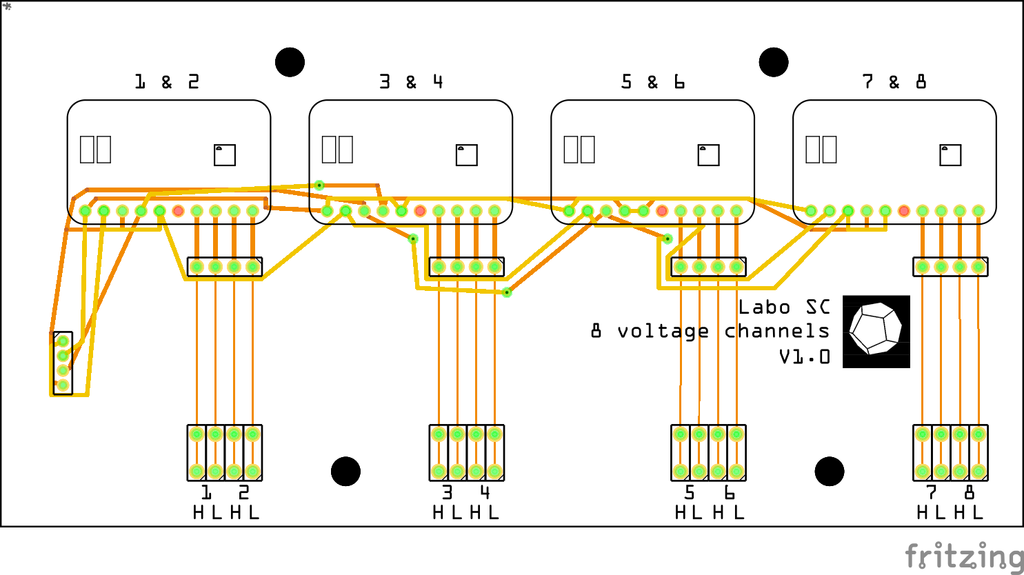
2. A second PCB, dedicated to the acquisition, has been designed in order to easily connect four analog/digital converters (ADS1115) per multiplexer's entry. The I2C address is successively set to 0x48, 0x49, 0x4A and 0x4B. Measurement wires are plugged to the PCB using lovely Phoenix Contact connectors. Multiple acquisition PCBs can be staked to each other in order to make a compact acquisition system.
The source code of the Arduino sketch is given herein-below. We here summarize the main point of the code. The code first manages the usage of the multiplexer. Behind each multiplexer output four ads1115 are connected.
First, general variables are set up. Specifically ads1115_array is an array containing the pointers of Adafruit_ADS1115 object.
typedef Adafruit_ADS1115* ads_ptr;


#define TCAADDR 0x70 //address of the TCA9548A multiplexer
#define VERBOSE 0

ads_ptr ads1115_array[8][4];

// the four possible adress's of each ads1115 module
uint8_t addr_ads1115[4] = {0x48, 0x49, 0x4A, 0x4B};
int init_value = 0;

int entry_status [8];
int stop_acq = 0;
Initialize ads1115_array variable.
void setup()
{
    while (!Serial);
    delay(1000);

    Wire.begin();


    Serial.begin(115200);
    Wire.setClock(400000);
    TWBR = ((F_CPU /40000l) - 16) / 2; // Change the i2c clock to 400KHz

    if (VERBOSE) Serial.println("\nTCAScanner ready!");

    for (uint8_t t=0; t<3; t++) {
      tcaselect(t);
      if (VERBOSE) Serial.print("TCA Port #");
      if (VERBOSE) Serial.print(t);
      if (VERBOSE) Serial.print("on address : 0x");
      if (VERBOSE) Serial.println(TCAADDR, HEX);

      for (uint8_t addr = 0; addr<=127; addr++) {

        uint8_t data;
        if (! twi_writeTo(addr, &data, 0, 1, 1)) {
            if (VERBOSE) Serial.print("Found I2C 0x");
            if (VERBOSE) Serial.println(addr,HEX);
        }
      }
      for (int j=0; j<4; j++){
        ads1115_array[t][j] = new Adafruit_ADS1115(addr_ads1115[j]);
        ads1115_array[t][j]->begin();

        if (VERBOSE) Serial.print("ADS1115 on address ");
        if (VERBOSE) Serial.print(addr_ads1115[j], HEX);
        if (VERBOSE) Serial.println(" initialized");
      }
    }
}
No acquisition is performed as long as no event on the serial port occurs.
The number of multiplexer entries that must be activated is set up through a first listening to the serial port. 8 consecutive characters are read. For instance, "10000100", meaning entries 1 and 6 (of the multiplexer) will activated.
Then the acquisition process is either started or stopped through the listening of one character : "0" or "1".
void serialEvent() {
  if (init_value==0)
  {
    for (uint8_t t=0; t<8; t++) {
      while(Serial.available()==0);

      char charValue[2];
      charValue[0] = Serial.read();

      int val = atoi(charValue);
      entry_status[t] = val;

    }
    init_value =1;
  }

  else
  {
    if(Serial.available()){
      char charValue[2];
      charValue[0]= Serial.read();
      stop_acq = atoi(charValue);

    }
  }
}
Loop over of each multiplexer entry, if activated, read of the 2 differential measurements of each of the four ads's. In total, there are 8 measurements per activated multiplexer entry. Each measurement is printed in the serial port.
void loop()
{

  if ((init_value==1) &&(stop_acq ==0)){
    double gain = 0.1875;
    String mesg = "";
    int16_t results;
    for (uint8_t t=0; t<8; t++)
    {
      if (entry_status[t]!=0)
      {
        tcaselect(t);
        if (VERBOSE) Serial.print("tca select ");
        if (VERBOSE) Serial.print(t);
        if (VERBOSE) Serial.print("on address : 0x");
        if (VERBOSE) Serial.println(TCAADDR, HEX);
        for (int j=0; j<4; j++)
        {
          ads1115_array[t][j]->setGain(GAIN_TWOTHIRDS);

          results = ads1115_array[t][j]->readADC_Differential_0_1();
          mesg += results * gain ;
          mesg += " ";

          results = ads1115_array[t][j]->readADC_Differential_2_3();
          mesg += results * gain ;
          mesg += " ";
        }
      }
    }
    Serial.println(mesg);
  }
  delay(10);
}A graphical user interface has been developed in order to perform easily the acquisition process. This tool, called ArDAQ, enables the users to manage the calibration, the recording and the monitoring of the acquisition. The source code is available on GitHub.
The software communicate to the module through the COM port. The software expects one line of data, per acquisition step, corresponding to all measurements performed by the module. That is, for n measurements, the data line reads :
"val_1 val_2.... val_i... val_n"
On the other side, the software sends 1 or 0 in order to tell the module to start or stop the acquisition.
Some snapshots are provided herein below.
The accuracy of the system has been assessed against a calibrated voltage source (accuracy 0.1%). A pack of 24 ads1115's has been verified using this reference. The chart below present the relative error as a function the imposed voltage (varying from -5.0 to 5.0 V).
The maximal error was found to be 0.12% without any complementary calibration. This value could be further diminished by means of dedicated calibration.
We have presented a solution for the acquisition and the monitoring of measurement using a 16-bit ADC. The Arduino-based solution is controlled via a Windows PC. For this purpose a dedicated tool (written in C#, called ARDAQ) is also proposed.
The system can be extended up to 8 x 8 measurements.


Comments