

Hardware components | ||||||
_ztBMuBhMHo.jpg?auto=compress%2Cformat&w=48&h=48&fit=fill&bg=ffffff) |
| × | 1 | |||
| × | 1 | ||||
| × | 1 | ||||
| × | 1 | ||||
PLEASE BE CAREFUL IF YOU’RE USING THE POWER LINE
Hello, and welcome to another tutorial, this one is about measuring Alternating Current (AC), using ACS712 I’m using the 30Amps version which is ACS712 30A, and our lovely Arduino Uno board, I tried to add an OLED screen but unfortunately ended up breaking it while shooting the tutorial so I switched to the LCD, but below you’ll find the wiring and codes for both versions.
And by “Any AC…” I mean that we gonna see a code/library that works for all signal types not only sinewaves one, and our Ammeter will be able to calculate the TRUE ROOT MEAN SQUARE. And note that the sensor uses the Hall Effect (production of a voltage difference across an electrical conductor, transverse to an electric current in the conductor and to an applied magnetic field perpendicular to the current)
You can combine this project with this one: Easy measure of AC Voltage using Arduino and ZMPT101B
Tests will be done on an incandescent light bulb, controlled by a light dimmer in series with a reference multimeter and the ACS712 current sensor module.
Here’s the plan:
- First we need to interface our module with the Arduino board and check the signal shape when the dimmer is ON – Full Cycle – Half Cycle.
- Then we gonna check a simple code that doesn’t require any library, but it works only with Sinewaves signal (it will be tested).
- After that we gonna see the code that will measure the TRMS of the AC, and use the LCD.
Please be carfeul when chosing the ACS712, don’t try to play it safe like I did (by purchasing a 30Amps version), this will just give big fluctuation when you try to use it for a domestic use or small amps applications, so here for me a 5A or 10A version would have been fine. Also note that 30A or 20A … will affect your calibrations too, but it’s explained how to calibrate in video and in codes comments.
Those are the parts I used, you can replace the UNO with any compatible board, or that LCD i²c with an OLED or any display you prefer.
Test 1Wiring and code
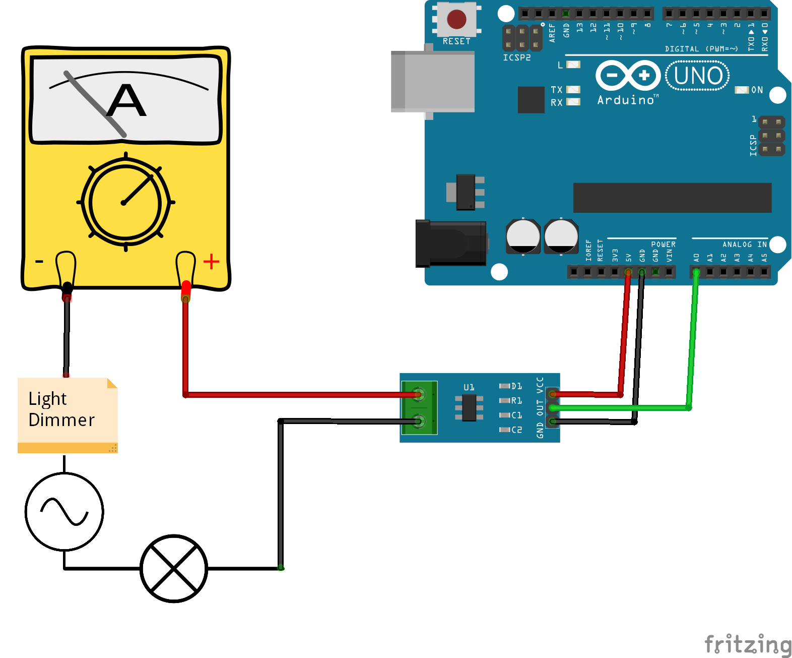
The wiring for test 1 can be found below (Wiring 1), alongside the code (Code 1).
Results
Upload the code and launch the serial plotter, you should be able to see a sinewave like signal, the red line shows when I turned down the dimmer and the current started having that shape that you usually find in a triac.
Now if you want to measure the current using the code above only, you’ll get values around 512 – 511, they don’t reflect the RMS value at all. So to measure the signal RMS value we gonna keep the same wiring as above but now we need another code that can calculate the RMS.
Wiring and code
The wiring is the same as (Wiring 1), but with a different code can be found below (Code 2).
Results
As you can see the values on the left (RMS) are the same as the value measured by the multimeter, on the right those are Peak to Peak values, and note that the dimmer is at full cycle as I’m using 75W bulb and 230VAC/50Hz.
!!!!!!!!!!!!!!!! BUT !!!!!!!!!!!!!!!!!!!!!
Here I turned all the way down my light dimmer, which means I’m approximately around 1/4 of a cycle, the multimeter is giving me 0.21A but my code gives me 0.36A, the code still measures from Peak to Peak, but as you can see above my signal is not linear when I turn the dimmer all the way down.
And that’s the difference between a TRMS measuring and a measuring that works only with sinewaves signal.
Test 3Now you see the problem of the code above, but fortunately there’s a library to the rescue, I really appreciate that library for all the work it does because as you know if you want to calculate a RMS value you need to use Integral Calculus, and that’s way difficult to achieve on an electronic development board, you can check the library cpp file to see what methods are used like the “Average” “Sigma”… Things related to statistics/probabilities ….
Wiring, code and library
The wiring is the same as wiring used above (Wiring 1), and below you can find the code (Code 3).
And Here you can download the Filters library: Download the library here
Results
The correct results are on the middle, the left ones are without calibration, and the right ones are used to demonstrate how to calibrate (check the video).
As you saw the huge difference between the two codes response to a non linear signal but the second one act as a TRMS multimeter.
Test with LCD/OLEDHere we keep the same things all we do is instead of using the serial monitor we can use LCD or OLED
Wiring, codes and libraries
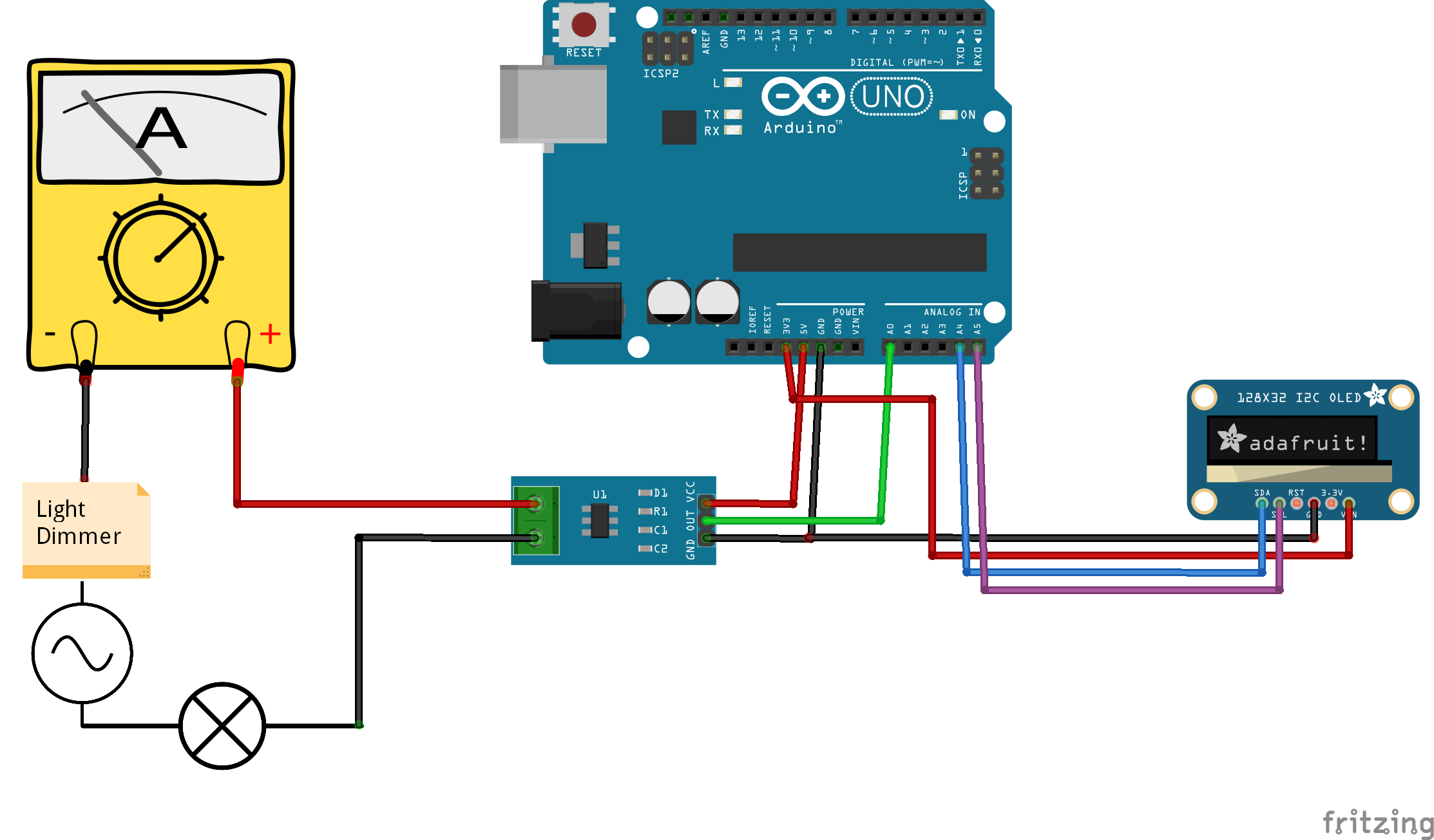
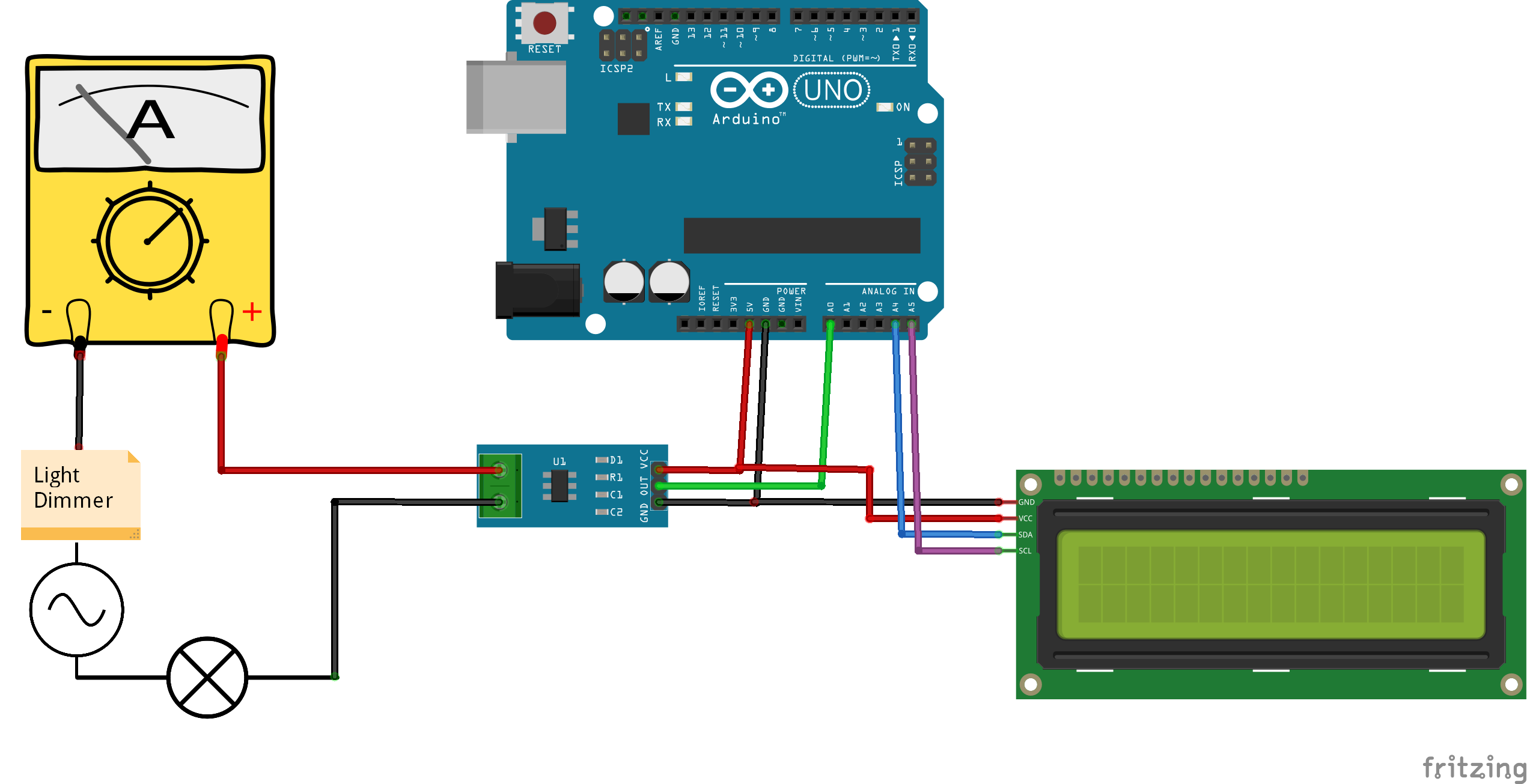
The wirings can be found below (Wiring_LCD) and (Wiring_OLED), codes also below (Code_ACS712_LCD) and (Code_ACS712_OLED).
Here are the OLED libraries
https://github.com/adafruit/Adafruit_SSD1306https://github.com/adafruit/Adafruit-GFX-Library
And here's the LCD_i2c_library
https://drive.google.com/file/d/1Oc56q2GPs5SOA-PdbVHHSxKCnI9KY5xd/view
Result
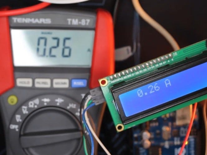
This is the only test I could do because I broke my OLED screen while trying to shoot the video tutorial. Overall this works the same way as we saw before, it just displays it on a LCD i²c screen. (Yes the TRMS values not the peak-to-peak method).
That’s all folks, I hope you like this tutorial don’t forget to like the video tutorial and subscribe to SurtrTech channel if you want to show support, thank you very much.
Any question leave it in the comments.


Comments