

Hardware components | ||||||
 |
| × | 1 | |||
| × | 1 | ||||
Software apps and online services | ||||||
 |
| |||||
| ||||||
 |
| |||||
Need to use this with Arduino? Check that: Easy measure of AC Voltage using Arduino and ZMPT101B
Please be very careful when you mess with the powerline !
Hello, everyone and welcome to SurtrTech channel, this is a project about how to measure any AC voltage (up to 250 VAC 50/60 Hz) using the ZMPT101B module, and by any I’m talking about the signal shape, because measuring a sinewave signal is quite simple but when it comes to some strange shapes like a triac’s one you need a special module and code like you gonna see here.
The project includes an example of Adafruit IO MQTT and another one about a small local Android App made in App Inventor 2.
This is an example of the signal shape when you use a Triac, here I will use a Triac based light dimmer, and in my previous tutorial when I used Arduino I showed that the code I’ve made performed much better than a cheap multimeter or a non TRMS multimeters.
This is the module I’m using, it’s called ZMPT101B, but actually this is name of the transformer (big blue thing), it has a LM358 Amplifier.
Depending on which board you’re using the output voltage will be different and also the offset, for Arduino the extremums were 0 and 5V with a 2.5V offset.
For the ESP8266 the extremums are 0 and 3.3V with a 1.65V offset.
This is why the module is good, it takes a signal that will burn your board and adapt it without losing its shape which is very important for a TrueRMS measuring.
About the power !When I tested this module with the Arduino board, it was very stable because I was using 5V, but when I wire it with the ESP8266 12E, I noticed some voltage drop, that’s why I used a Li battery and a converter to keep the power stable (3.3 VDC).
I don’t know, maybe because I have an old board (2017), ESP8266 12E (NodeMcu V1.0), or the board is not drawing enough power from the USB cable…. but if it works for you it’s pretty much the same thing for these kind of boards, even the 5V ones.
First calibrationHere we want to calibrate our module first, using the built-in potentiometer, to adjust the signal amplification.
Like I explained before, theoretically, the 250 VAC (RMS) signal should be reproduced as a signal that goes from 0 to 3.3V and centred around 1.65V, which means we can exploit all the ADC range which is 0 – 1023, and it will be more precise to calculate the values.
But unfortunately we cannot do that, as the signal can be lost at some points, so we have to reduce the amplification and instead of exploiting all 0 – 3.3V we’ll have to work with a smaller range, and that’s why using 5V boards is better.
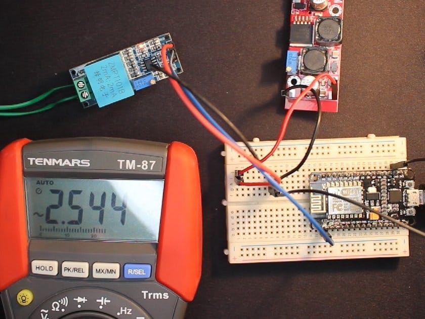
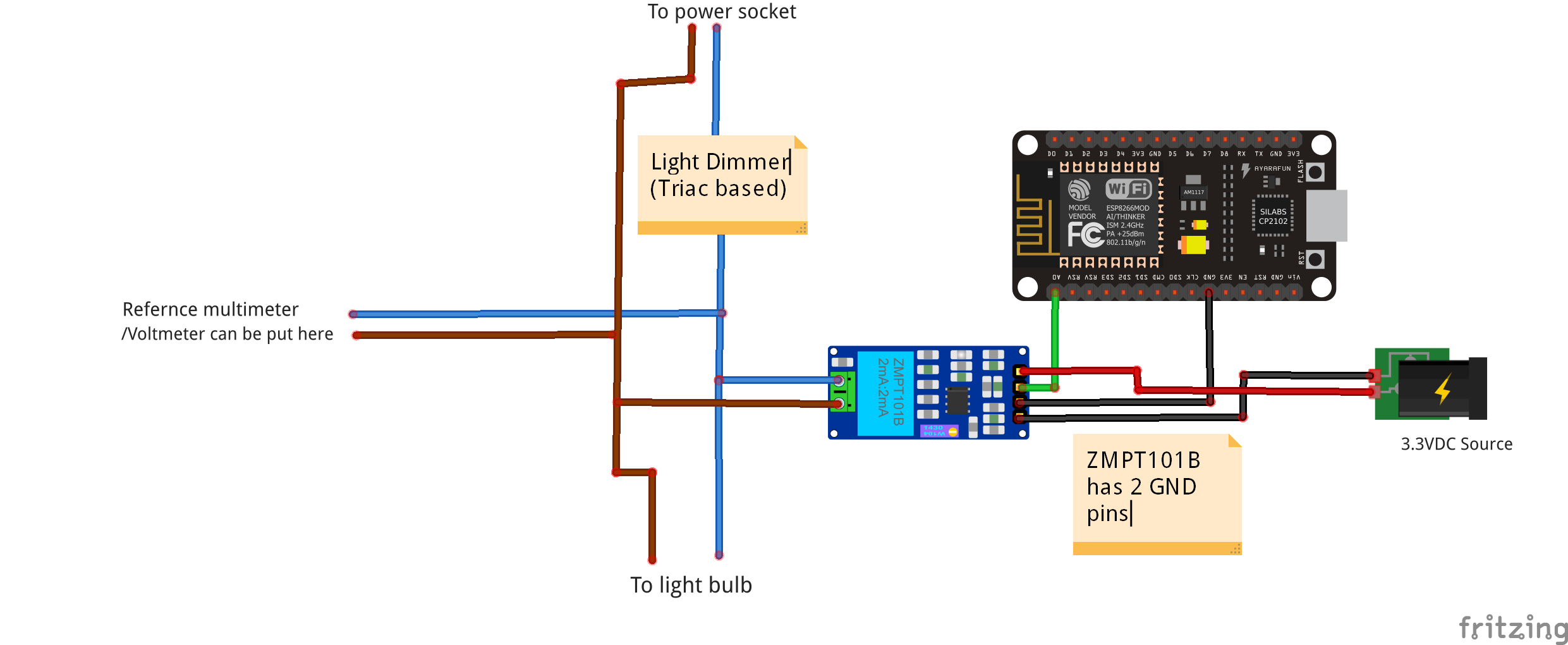
WiringHere in the wiring I have the module hooked up with the board, and I have also my test bench, I’ve choosen to measure the Voltage of an incandescent light bulb wired with a Triac based light dimmer, you can measure what you want.
All you have to do now is put the MAXIMUM voltage (without surpassing 250VAC), in my case I have around 230V/50Hz, you can take it directly from the socket or after A full cycle light dimmer.
CodeNow you upload that code and open the Serial Plotter of the Arduino IDE.
void setup() {
Serial.begin(115200);
pinMode(A0,INPUT);
}
void loop() {
Serial.println(analogRead(A0));
//delay(100);
}
Yes this the code that you’ll need for the moment, that delay you can keep it or remove it you’ll notice the difference once you test both (or check the video above).
CalibrationOnce you open the Serial Plotter you gonna see some shapes passing by.
This is what you don’t want: A shape that has an horizontal straight line on the extremums….
This is what you need to see: Some Sinewave like signal, so keep turning your potentiometer until you can see something like this, and pay attention here you are controlling the signal amplification, so you need to have the maximum values without disturbing the shapes.
Once this is done, and keep in mind that you shouldn’t keep turning it because it will affect all future calculations.
True RMS measuring and calibrationHere we gonna see the important code for measuring the TRMS value, but it should be calibrated first, and once you start measuring “correctly” the values you can do whatever you want with your values: Send them via MQTT, create a small App, use with Blynk….
First you should put 0 VAC as the module input, of course you can keep the same wiring.
LibraryDownload the Filters library here !
Or check down below.
CodeCode is down below
This is the code that you can use first to get familiar with the library, measuring and calibration, it doesn’t have a third party or in need to be connected to the WiFi, all it does is measuring the TRMS values and display them on the Serial Monitor, and of course you can recalibrate as you need when you use other things.
Those are pretty much the three important parts of the calibration:
For the windowLength, with Arduino I used “40/testFrequency” it was nice but with the ESP8266, the “100/testFrequency” gave better results, you can try and see what suits you the most.
For the moment it’s better to keep the intercept and slope as they are, and as you can see they don’t change the “Sigma” which is what we calculate in this code.
Once you upload the code open the serial monitor, do not forget 0VAC as the input.You’ll see something like this:
There are some fluctuations, it’s not that big, normally if I had a stable value there like 1.88, the intercept will be then -1.88, so what you need to see there is 0 or close to 0. In my case I kept the intercept as 0.
Now put the intercept value as you found better and reupload the code to the board.
Also put the AC input at some value, for example your network RMS, measure it using the multimeter to get the right value, and open again the serial monitor.
Those are the values I got it was around “90.5” in calibrated. (They are the same because the intercept is 0).Measured with the multimeter “228.6”.
So the Slope will be = 228.6/90.5
Apply the new slope to the code, you can discard the “non calibrated value”.
This is pretty much the difficult and most important task to achieve, once you get this you can add some WiFi or Internet functions as you want, I’ve chosen some few to put here as example.
Using with Adafruit IO MQTTNow that you are able to measure the AC voltage you can send those values to a third party, here I took the Adafruit IO MQTT as example.
“”There’s no detailed tutorial for this at the moment, let me know if needed””
Once you sign-in there, you should go to Feeds and Create a new feed (Pay attention it’s not unlimited). I’ve created a feed and named it “Test”.
Remember the name it’s important !
Then you go to Dashboards, create one and add a new block, here I added a Gauge.
Every Gauge need a feed so you chose the one you’ve created before.
And you adjust the settings as you need.
Now you’re ready to go all you need are some libraries and a suitable code.
LibrariesIt’s better to go to the Arduino IDE Library Manager, and search for these ones below, if it asks you to download some other libraries because they are essentials, let it install them.
Code is down below
In the code don’t forget to modify these things:
the “Test” is jut my Feed name !! You should replace both by your feed name.Of course then you’ll have your own slope and intercept as we said before.
ResultThis is an example of the result, of course those values can be stored for some time, depending on you account settings, you can add some warnings if you want.
No tutorial about how to make this app with details is available, let me know if you need any.
In this section I’ve add a small App for Android that I made using MIT App Inventor 2.
This is how the app looks like, it’s a beginner thing to make you start, once you connect your ESP8266 to the Wifi it will have a local IP address, you can see it in the Serial monitor when the ESP8266 starts.When you set your IP address press Connect, this will set which address to use for communication, and stores it in a database to be used later when you restart you app.
To get the Value press “Get Value”.
I kept in the code in case you want to send it as html format, just uncomment the lines.
Here you can download the app “.apk” so you can install it and use it.
CodeCode is down below.
The code is very simple, it just sends the data whenever a client tries to connect to it, to use with multiple sensors it should be more elaborated.
ResultPower OFF
Power On, light dimmer turned a little:
If you’re into Mobile App Development, you can of course create a more elaborate app, with warnings if you want, notifications and most important to be able to connect via internet not only locally like this one.
There are some few modifications to do for example using Adafruit IO or ThingSpeak… to be able to get the data via internet using only this simple App created in APP Inventor.
That’s all folks.


Comments