

Hardware components | ||||||
_ztBMuBhMHo.jpg?auto=compress%2Cformat&w=48&h=48&fit=fill&bg=ffffff) |
| × | 1 | |||
| × | 1 | ||||
 |
| × | 1 | |||
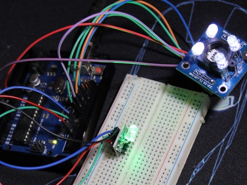
Hello, in this tutorial we’ll be using the TCS3200, TCS230 or GY-31, color sensor module with Arduino UNO board, and there will be project using a RGB LED to reproduce detected colors.
The module has an 8×8 photodiode array, 16 of them with Red filter, 16 with blue one, 16 with green one and 16 without a filter (clear), we select what filter to use and read its value, and in the code we combine them depending on the applciation or project.
The light is detected by the photodiodes and the output is a frequency proportional to the current flowing through the photodiodes which is related to the filter used and the object’s color detected.
-The module has (Vcc/GND) pins, they are redundant.
– S0/S1 pins control the output frequency scalling
– S2/S3 pins control which set of photodiodes we gonna measure (Red/Green/Blue/Clear)
– Out is the output signal and LED pin controls the LEDs on the front.
This option permits the module to be used with different measuring techniques, and types of microcontrollers, in the tutorial and codes I kept using it at 100%, you can change it if you want it depends just on the logic level of their pins (HIGH/LOW).
By also controlling the logic levels of S2/S3 we can select which filter or no filter to use, in the code I go through Red/Green/Blue, if your application require one or two filters only you can do it too.
For the LED pin, if it’s not connected, the LEDs will light up automatically, but if you want to turn them off you can put the LED pin to LOW, (it depends on your application and condition).
For the Out pin, as the signal given by the sensor is a frequency, we measure the duration as they are related (Duration=1/Frequency), so the higher the frequency of a color, the lower is the duration measured, which means that the object detected has that color (check the tutorial).
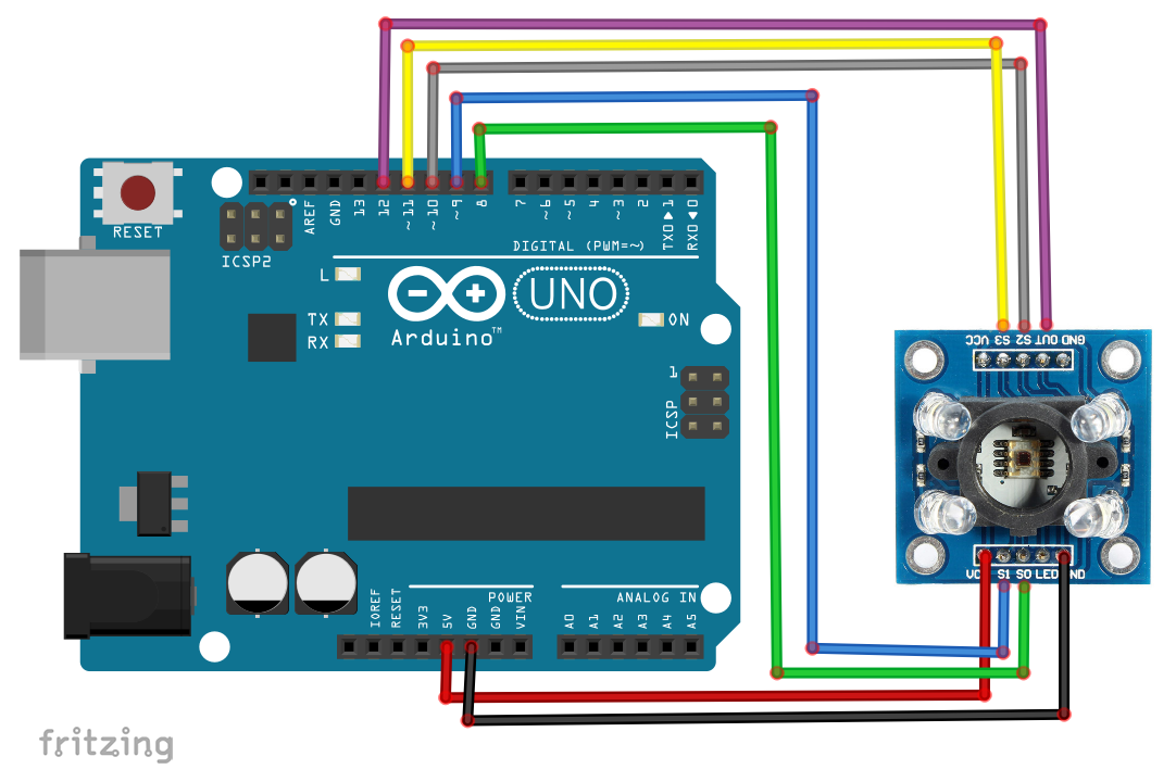
PartsAlongside some jump wires, this is what we need
Wirings are below and here are some comments
Vcc/GND are the same chose which one you want to use, pay attention some modules have « OE » pin, leave it on LOW level otherwise it turns off the module
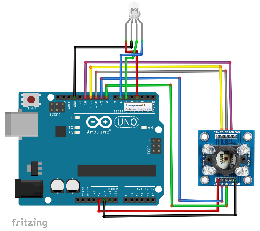
Don’t forget the RGB should be connected to PWM pins and here I have a common cathode one.
CodesCodes are below too
Code 1: Is just direct wiring and reading the output signal for Red/Blue/Green, you can use it to calibrate your module, for example place some object and check the sensor values, because those values are related to the lighting conditions, exposure, and the object itself.
Code 2: Now we have an idea about the values for each color, we can start identifying them, the easy method is that during first tests you’ll notice that the color of the object has the lowest value, which is a duration, (higher frequency), check tests below.
.Code 3: Here we are using the RGB LED, and we try to reproduce the values of the colors given by the sensor, and most of the time it reproduce the color of the object detected, here what you should know: the min/max value given by the sensor for each color, and that it’s inverted (the lowest the value, the higher is the color).
analogWrite(LED_R,map(Red,15,60,255,0));
This is the function we used, so we generate a PWM signal with « analogWrite », on the pin (LED_R) which is the Red pin for the RGB LED connected to pin D3, the value we write is proportional to « Red » value which is the Red value given by the sensor, and it has 15 as minimum and 60 as maximum (those are my proper values, try measuring your own), and this value is converted to 255-0, so the 15 will be « equal » to 255 and 60 will be « equal » to 0For example if the module gives us « 15 », the LED_R will receive « 255 » value which is the highest (5V), because as said the lower the value the higher is the color)…
TestsTest 1
This is the Test of the Code 1, the RGB values of its object is displayed in the Serial monitor and as you can notice, the RED value is the lowest one
Test 2
Here in the code 2, we don’t display the values, but the color of the object if identified, here we have green object and green is detected
Test 3
Code 3 test, the blue color of the notebook is reproduced with the RGB LED
Add-ons- In the code 2, you can add as many colors as you want just measure their values
- Don’t change a lot the module placement and lighting when calibrating the module
- For the RGB code, the blue is very dominating, you can try to reduce it


Comments