
Hardware components | ||||||
 |
| × | 1 | |||
 |
| × | 1 | |||
 |
| × | 1 | |||
 |
| × | 1 | |||
 |
| × | 1 | |||
Software apps and online services | ||||||
 |
| |||||
In this tutorial, we will integrate the Surilli Basic M0 with an HC-SR04 ultrasonic sensor module and then visualize the changing distance values on the 16x2 LCD.
Ultrasonic Sensor (HC-SR04):The HC-SR04 ultrasonic sensor module has 4 pins: Ground, VCC, Trig and Echo. The Ground and the VCC pins of the module needs to be connected to the Ground and the 5 volts pins on the Surilli board respectively and the trig and echo pins to any digital I/O pin on the Surilli board. Trigger (Transmitter) emits an ultrasound at 40, 000 Hz which travels through the air and if there is an object or obstacle on its path it will bounce back to the Echo (receiver). Considering the travel time and the speed of the sound you can calculate the distance.
In order to generate the ultrasound you need to set the Trig on a High State for 10 µs. That will send out an 8 cycle sonic burst which will travel at the speed sound and it will be received in the Echo pin. The Echo pin will output the time in microseconds the sound wave traveled.
For example, if the object is 10 cm away from the sensor, and the speed of the sound is 340 m/s or 0.034 cm/µs the sound wave will need to travel about 294 u seconds. But what you will get from the Echo pin will be double that number because the sound wave needs to travel forward and bounce backward. So in order to get the distance in cm we need to multiply the received travel time value from the echo pin by 0.034 and divide it by 2.
Liquid Crystal Displays (LCDs):A 16x2 LCD has 2 horizontal rows each comprising of 16 displaying character. This means that a total of 32 characters can be displayed on a 16x2 LCD. An LCD is used in many electronics projects to display the status of the process, voltage levels, sensor values, system health and the list goes on n on. Lets now cut the theory part and jump to the hands-on experience.
Pin Numbering:The PIN numbering goes from left to right (1 - 16).
Required Hardware:1. Surilli Basic M0.
2. 16x2 LCD.
3. Ultrasonic sensor module (HC-SR04).
4. Connecting wires.
5. Arduino IDE software.
Connections:Ultrasonic Sensor Module (HC-SR04) with Surilli Basic M0:
- -> PIN TRIG (HC-SR04) to PIN 9 (Surilli Basic M0).
- -> PIN ECHO (HC-SR04) to PIN 10 (Surilli Basic M0).
- -> GND PIN (HC-SR04) to GND PIN (Surilli Basic M0).
- -> VCC PIN (HC-SR04) to USB PIN (5V) (Surilli Basic M0).
16x2 LCD with Surilli Basic M0:
- -> VSS PIN (LCD) to GND PIN (Surilli Basic M0).
- -> VDD PIN (LCD) to 5V PIN (Surilli Basic M0).
- -> V0 PIN (LCD) to GND PIN (Surilli Basic M0).
- -> RS PIN (LCD) to 6 PIN (Surilli Basic M0).
- -> RW PIN (LCD) to GND PIN (Surilli Basic M0).
- -> E PIN (LCD) to 11 PIN (Surilli Basic M0).
- -> D4 PIN (LCD) to PIN 5 (Surilli Basic M0).
- -> D5 PIN (LCD) to PIN 12 (Surilli Basic M0).
- -> D6 PIN (LCD) to PIN 20 (Surilli Basic M0).
- -> D7 PIN (LCD) to PIN 21 (Surilli Basic M0).
- -> A PIN (LCD) to 5V PIN (Surilli Basic M0).
- -> K PIN (LCD) to GND PIN (Surilli Basic M0).
Make sure you have selected the right port, board and processor for the Surilli as shown in the picture below and it is programmable (compile and upload “Blink” from File>Examples>Digital>Blink onto your Surilli to check if every thing is working fine).
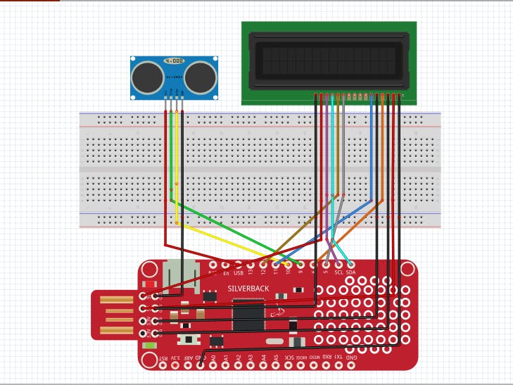
STEP 2: The CircuitryThe circuitry is a little complex so we will go through it first. Complete your circuit connections and then move on to the next step. It's mostly the programming. Follow the figure below to set up your hardware.
- Now you have completed setting up your hardware and Arduino IDE. Copy and paste the Arduino sketch given below into your Arduino IDE and hit upload.
- After the Arduino code has been uploaded, the changing values for the distance can be viewed on the 16x2 LCD screen. As soon as you place any object towards or away the ultrasonic sensor, the distance values changes accordingly.
#include <LiquidCrystal.h> // Include the LiquidCrystal Library.
LiquidCrystal lcd(6, 11, 5, 12, 20, 21); // Creates an LCD object. Parameters: (rs, enable, d4, d5, d6, d7).
const int trigPin = 9;
const int echoPin = 10;
long duration;
int distanceCm, distanceInch;
void setup()
{
   lcd.begin(16,2); // Initializes the interface to the LCD screen, and specifies the dimensions (width and height) of the display.
   pinMode(trigPin, OUTPUT);
   pinMode(echoPin, INPUT);
}
void loop()
{
   digitalWrite(trigPin, LOW);
   delayMicroseconds(2);
   digitalWrite(trigPin, HIGH);
   delayMicroseconds(10);
   digitalWrite(trigPin, LOW);
   duration = pulseIn(echoPin, HIGH);
   distanceCm= duration*0.034/2;
   distanceInch = duration*0.0133/2;
   lcd.setCursor(0,0); // Sets the location at which subsequent text written to the LCD will be displayed.
   lcd.print("Distance: "); // Prints string "Distance" on the LCD.
   lcd.print(distanceCm); // Prints the distance value from the Ultrasonic Sensor (HC-SR04).
   lcd.print(" cm");
   delay(10);
   lcd.setCursor(0,1);
   lcd.print("Distance: ");
   lcd.print(distanceInch);
   lcd.print(" inch");
   delay(10);
}
Follow the link below to see the live video demonstration of the project:
Play with the program to see how it reacts to different values and logic.
If you make something fun and interesting do share it with our community.
That’s all for now. If you have any queries, visit surilli.io or contact our support. Stay connected with Surilli family for more amazing stuff. :-)


Comments