


Hardware components | ||||||
_ztBMuBhMHo.jpg?auto=compress%2Cformat&w=48&h=48&fit=fill&bg=ffffff) |
| × | 1 | |||
| × | 1 | ||||
| × | 1 | ||||
| × | 1 | ||||
| × | 2 | ||||
| × | 1 | ||||
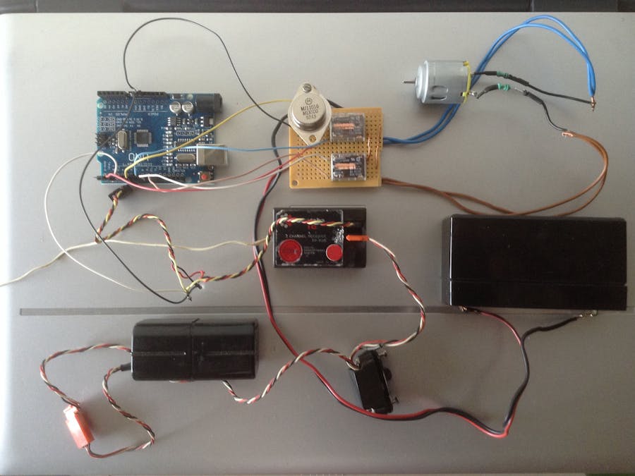
I have a small RC tugboat, built in the '80s, with 2 channels (throttle and rudder) and 2 servos. All I would like to do was to replace the old fashioned Forward-Reverse switch of the motor with an electronic speed controlled device so that I can vary the speed of the propeller from neutral to full forward (or full reverse) in a variable way rather than in a "step" ON-OFF one.
The first thing to do is to understand what kind of signals the RC receiver sends to the servo motors.
A typical receiver sends pulses PWM to the servos. Arduino has a built-in function to detect these pulses and it is called pulseIn(). This function reads a pulse, measures the time of the duration and returns the length of the pulse in microseconds. The simple sketch below "The intermediate code" is for understanding the values that the RC receiver sends over and prints the raw input of the receiver to the serial monitor.
For this purpose, the following configuration is necessary:
- Connect the signal pin cable ("white' cable in my case) of the RC receiver's throttle channel to Arduino pin no. 5
- Connect the negative pin cable ("black' cable in my case) of the RC receiver's throttle channel to Arduino earth pin
- Connect the RC receiver to its power supply
- Switch on the RC transmitter
- Move slowly the throttle from "neutral" to "upmost forward" position. Then move slowly the throttle from "neutral" to "undermost reverse" position
- Keep track of the readings in the monitor.
By running the aforementioned sketch I get values from 800 to 1700μs; in particular:
- From "neutral" to "upmost forward" position, values from 1250 up to 800μs
- From "neutral" to "undermost reverse" position, values from 1250 to 1700μs
The second thing to do is modify the above values into context, that is translate the values into voltage signal of 0-5V in order to drive the motor through a power transistor.
For this I used the analogWrite() function which writes an analog value to a pin which drives the motor, in this case pin no. 3 (see "The final code"). The map() function translates the 1700-800μs range onto the 0-255 range which is appropriate for the analogWrite function. In other words, when the throttle moves from "neutral" to "forward", that is from values 1250 backwards, Arduino maps them as values from 0 to 255 and sends a variable voltage of 0-5V to pin no.3.
In the opposite direction, when the throttle moves from "neutral" to "reverse", that is from values 1250 onward, Arduino maps them as values from 0 to 255 and sends a variable voltage of 0-5V to pin no.3.
For safety reasons the if() function makes sure a dead section of 1000μs (500 each side of neutral position) is left without sending any signals.
The resistor just before the transistor's base (see the "Confifuration diagram") appears to be 10KΩ. Note that the exact value of the resistor needs to be calculated for optium results and depends on the technical characteristics of the motor. In this project the motor is relatively of low power (apprx. 5W), but in the case of more powerful motors, care should be taken as the rated current of the OMRON relays is limited to 8A.
From the above it is obvious that irrespective of the movement of the throttle, that is "forward" or "reverse" position, pin no.3 sends the same variable voltage 0-5V to the power transistor in order to drive the motor.
The third thing to do is to teach Arduino to reverse the polarity to the motor when throttle is in the "reverse" position.
For this, a pair of single coil latching relays is used and its operation is triggered by a pulse from Arduino. The pulse lasts for 30ms and is driven to pins no. 6 and 10 when the throttle is in "forward" position and to pins no. 9 and 11 when in "reverse".
In this way, both relays lock and retain the polarity to the motor until the next pulse from Arduino comes in.
Finally, the "Improved configuration diagram" differs from the aforementioned "Configuration diagram" in the way that instead having a separate 6V battery pack to power the RC receiver, the latter one is powered by the same 6V battery which powers both the motor and Arduino.
The speed controller inside the tugboat operates as it is shown on the video.


Comments