

Hardware components | ||||||
| × | 1 | ||||
| × | 1 | ||||
 |
| × | 1 | |||
Software apps and online services | ||||||
| ||||||
 |
| |||||
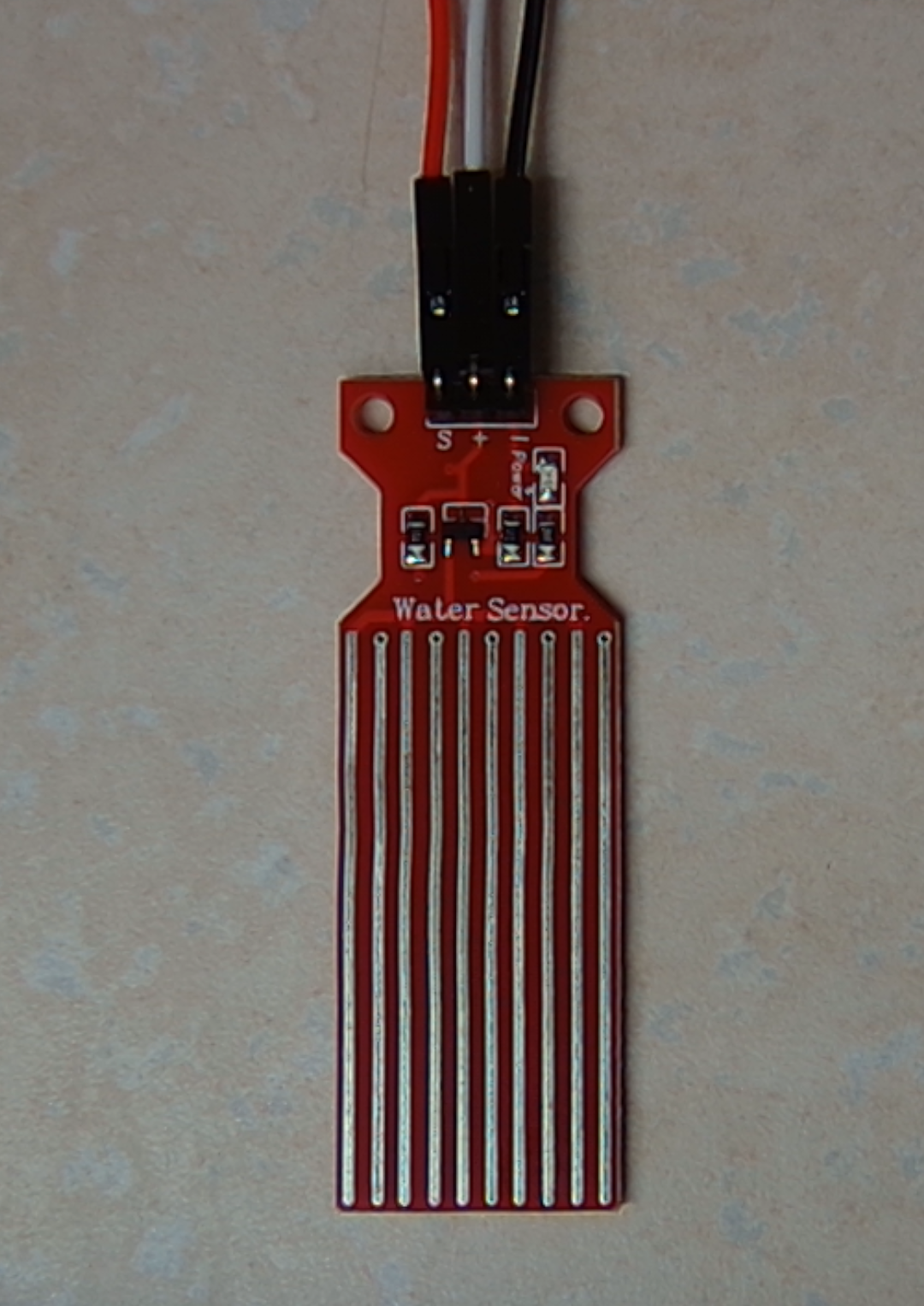
This project is designed to detect flooding in remote and/or low-traffic areas (such as basements and sheds) utilizing affordable parts able to be purchased in small and large quantities. The selected water sensor board is Adafruit 4965 (DigiKey Part Number 1528-4965-ND). If unavailable, the design is somewhat generic, with interchangeable parts available on Amazon and Alibaba. This design also utilizes female DuPont connectors to ensure that sensors can be easily replaced if necessary due to damage or corrosion from use in particularly damp environments.
This tutorial does not include a housing for the module. I strongly suggest commercial and industrial users design a housing when incorporating it into a finished product. If mounting the Muon further than 1ft / 30cm away from the sensor, you may need to terminate your own cut-to-length cables as cables of this type are typically harder to obtain in longer lengths. The process of stripping and terminating 2.54mm pitch DuPont connectors is beyond the scope of this tutorial.
This flood detection device is intended to be installed with the liquid level sensor aligned vertically with the bottom edge touching the floor and the wires going directly up. If the location is uneven, the lowest area is the ideal installation location, as this is where water is first to pool. If there are no available outlets, the Muon is compatible with 3-pin 3.7v LiPo batteries such as the US Electronics USE-18650-2600PCBJST (DigiKey Part Number: 3544-USE-18650-2600PCBJST-ND).
AssemblyFirst, identify the three pins on your water sensor. They should be labeled “-”, “+”, and “S”.
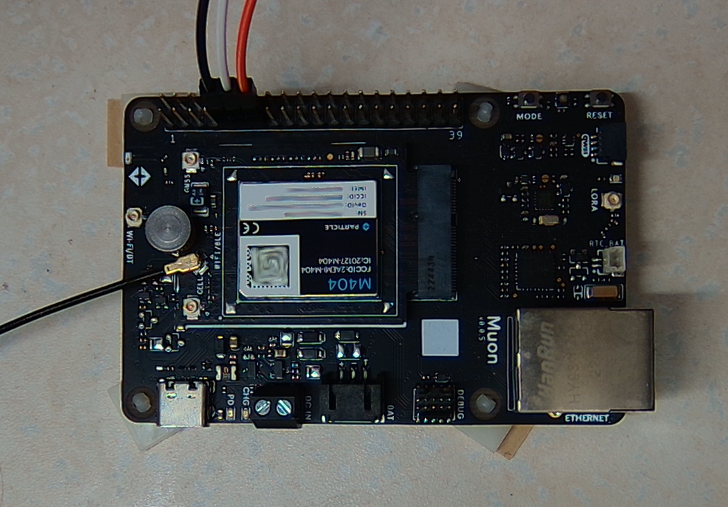
While your Muon is disconnected from power, connect a cable from the - pin on the sensor to a ground pin on the Muon's 40-pin header array — I recommend pin 9. If oriented with the header array to the top of the board, this is the fifth pin from the left on the bottom row.
Next connect a cable from the + pin on the sensor to a digital pin on the Muon. I recommend using D2, which is Pin 11 and directly to the right of pin 9.
Finally, connect a cable from the S Pin on the sensor to an analog pin on the Muon. Conveniently, pin A5 is also Pin 13 and located directly to the right of your previously installed pin.
At this point, power up your Muon and open either Visual Studio Code OR your Particle.io WebIDE so we can program our M404 to use the sensor and connect to send an alert when water is detected.
In your IDE of choice, create a new project. The WebIDE will always start a new project with the following and we want to keep it for our purposes
// Include Particle Device OS APIs
#include "Particle.h"

// Let Device OS manage the connection to the Particle Cloud
SYSTEM_MODE(AUTOMATIC);

// Show system, cloud connectivity, and application logs over USB
// View logs with CLI using 'particle serial monitor --follow'
SerialLogHandler logHandler(LOG_LEVEL_INFO);

// setup() runs once, when the device is first turned on
void setup(){
}
    void loop(){
}
--------------------------------------------------------------------
At this point, we have some variables to declare. Do this after the line dealing with SerialLogHandler but before void setup(). We should start with the pins we need to turn on. Luckily, GND does not need any interaction, so we don't need to deal with it. We could use the 3v3 pin to provide constant power to the sensor, but some users may want to power their Muon via a battery and this saves on power consumption.
int powerA = D2;
int signalA = A5;
Now that we've defined our pins, we also have a couple variables we'll need for our actual code logic. The first will be used to store the sensor data, and the other will be utilized as a flag to signify that an alert has already been triggered to prevent a flood of alerts. We'll declare these below the pin declarations.
int valA = 0;
bool alerted = 0;
The alert is a bool because we only ever evaluate if it's on or off. Any value other than 1 or 0 would indicate something has failed dramatically.
Now we move to the setup() to set the pinMode for the power pin. This makes our setup phase read as follows:
void setup(){
    pinMode(powerA, OUTPUT);
}
On the Muon, all I/O pins are digital input pins at startup, so we don't need to assign a pinMode to our sensor pin.
The main loop is where the M404 actually does the checking of the sensor and alerting. We begin by turning on the digital pin we're using for power after a bit. We then wait for 1 second, read the sensor's value to our defined variable, then turn off power to the sensor. The code for that is as follows:
delay(100);
digitalWrite(powerA, HIGH);
delay(1000);
valA = analogRead(signalA);
digitalWrite(powerA, LOW);
It should be noted that some sensors have capacitors large enough to keep the on-board LED lit for over a second. You may see it pulse or it may just stay on.
Next we have to take action on what the sensor data shows. We should evaluate to see if the sensor has anything more than some condensation or board variation. I found one of my dry sensors showing 0 with occasional spikes up to 2. To avoid a false positive, we want to look for spikes over 5, which would denote some water is definitely present, but still low enough to allow for a timely response. If the sensor detects water, it should publish an alert, and set our alerted flag to 1.
if (valA >= 5){
    Particle.publish("FLOOD ALERT - Sensor A - Water Level:", String(valA));
    alerted = 1;
}
Since this is to generate an alert regarding an urgent matter, we don't want to send an alert every 1.1 seconds, so we check to see if we've been alerted and, if we have, delay further activity. Normally, we would check to see if a specific number of milliseconds has passed instead of using delay() to avoid blocking processes, but we don't want the board to do anything else. As such, we can delay here for legibility.
if (alerted == 1){
    delay(600000);
}
I opted for a 10 minute delay between published events to give time for response.
All together, the source looks like this:
#include "Particle.h"

SYSTEM_MODE(AUTOMATIC);
SerialLogHandler logHandler(LOG_LEVEL_INFO);
int powerA = D2;
int signalA = A5;
int valA = 0;
bool alerted = 0;

void setup(){
    // Sensor pinMode
    pinMode(powerA, OUTPUT);
}

void loop(){
    delay(100);
    digitalWrite(powerA, HIGH);
    delay(1000);
    valA = analogRead(signalA);
    digitalWrite(powerA, LOW);
    if (valA >= 5){
        Particle.publish("FLOOD ALERT - Sensor A - Water Level:", String(valA));
        alerted = 1;
    }
    if (alerted == 1){
        delay(600000);
    }
}
--------------------------------------------------------------------
I’ve uploaded the source to my GitHub account — it may include improvements made after this tutorial was created.


Comments