

Hardware components | ||||||
_ztBMuBhMHo.jpg?auto=compress%2Cformat&w=48&h=48&fit=fill&bg=ffffff) |
| × | 1 | |||
 |
| × | 1 | |||
 |
| × | 1 | |||
 |
| × | 1 | |||
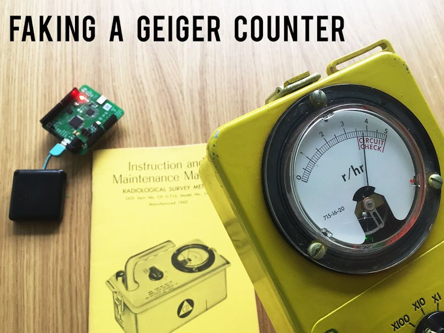
A number of projects exist to fake a Geiger counter's unique sound. Unfortunately, they only fake the sound, not the sensor that measures the radioactive material. In this project, I wanted to completely fake a Geiger counter using indoor positioning to make the Geiger counter go off when approaching specific locations. This project does not require any radioactive material!
I made two variations, one that is based on the distance between the Geiger counter and some other device, and another variation based on the position of the Geiger counter. You can see it in action here, watch the gauge on the device as the tag comes closer.
Why did I built this?I work at Pozyx, and after doing an escape room game, I imagined how indoor positioning could be used to make the escape room more interactive. For people that don't know the concept of an escape room: it is a game you play with friends where you are locked up for 1 hour in a room and have to solve riddles to get out. This is how I came up with the fake Geiger counter. You can use it to have people look for some hidden clues within a post-apocalypse setting or a nuclear missile-base.
Components- Arduino: This is where the code will run.
- Pozyx tag: The pozyx tag is an Arduino compatible shield that can perform wireless ranging or positioning with an accuracy of 10cm using ultra-wideband (UWB) technology.
- Pozyx anchor(s): Ranging happens with another Pozyx device, whereas for positioning 4 anchors are required (similar to GPS). The Pozyx system is sufficiently accurate and robust against obstacles or reflectors in the environment to make it ideal in an indoor environment. It even keeps on working when placing the system in a metal Geiger counter casing.
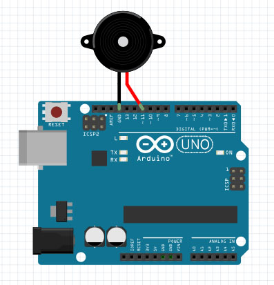
- Buzzer: The buzzer is used to create the sound. If you don't think the buzzer is loud enough, you can check out this older tutorial that uses a speaker to replicate the Geiger counter sound.
A Geiger counter has a very unique crackling sound. We want to emulate this sound with a simple buzzer and make the intensity go up when closing in on the anchor. To recreate the characteristic sound I did the following things:
- Add a base delay between sound beeps that is proportional with the distance to the target, with a maximum base delay of 3 seconds.
- On top of the base delay is a random variation of up to 150ms.
- There is a 20% chance that there is no delay at all. This will make the characteristic crackle every once in a while.
- The frequency tone of buzzing is random between 350 and 550kHz.
You can still play with the numbers above to change the sensitivity of the Geiger counter. Here is a plot of the buzzer going off when closing in on the anchor.
The geiger counter sound depends on the distance to the target. With the Pozyx system, this can be the distance measured between a tag and an anchor. Alternatively, when the Pozyx system is used for positioning, the distance can be related to any point you define in space. This allows us to set of the Geiger counter in places without any physical device. Awesome!
The easiest to start is just using the ranging with an anchor. So check out the first sketch below. For the positioning, we need to set up 4 anchors and measure their positions first. This can be done manually or with the Pozyx web interface. I will let you all write the code for the positioning case, it should be really easy.
Old-school casingTo create an authentic experience, we can put our fake Geiger counter in a proper casing. On ebay, I found the 'radiation survey meter 715', which is an old-school Geiger counter from the year 1962 that we can easily dismantle. The counter comes with an analog gauge, a rotary selector to select modes and a control knob to adjust the zero offset. Depending on how much effort you wish to put in, you can incorporate all these elements in the final fake Geiger counter.
Dismantling
Start by dismantling the device by opening the hood and unscrewing 8 screws. To get the PCB completely out, I had to desolder the potentiometer that was connected to the control-knob and detatch the two wires connected to the gauge.
Gauge
The gauge can move its needle between 0 and 5 Roentgen / hr. We can move the needle by applying a voltage between 0 and 85mV (17mV is approximately 1 r/hr). We can use the PWM output (for example digital pin 3) of the Arduino to move the needle. The Arduino can output the voltage between 0 and 5V in 256 steps (using pulse width modulation). Because we need a finer resolution, I used a voltage divider. This is done by placing two resistors in series between the PWM pin and the ground (11kOhm and 2.7kOhm), and connecting the point in between the resistors to the gauge. This divides the output approximately by a factor 5.
Rotary selector
The knob has 6 fixed positions (60degrees between each knob position). This is something we can measure with a potentiometer. Although the knob is designed to change the reading resolution, it is more fun to use it to lock on to another anchor.


Comments