


Hardware components | ||||||
_ztBMuBhMHo.jpg?auto=compress%2Cformat&w=48&h=48&fit=fill&bg=ffffff) |
| × | 1 | |||
 |
| × | 1 | |||
| × | 1 | ||||
 |
| × | 1 | |||
 |
| × | 1 | |||
 |
| × | 1 | |||
Software apps and online services | ||||||
 |
| |||||
In this machine, user have to swipe RFID card across(4cm) RFID reader. After five second, it will give fixed amount of fluid as per defined in Arduino sketch. Every activity will be displayed on Alphanumeric LCD as per operation, which will help user to follow instruction while taking fluid. This machine could be implemented in organization like hospital, college (medical, engineering etc.) to provide human independent facility.
There is a vital importance in many places, where it would solve problem, which are following: -
- In hospitals, patient need milk. They can get easily, no need to go in outside market, which is far away.
- In educational organization, where shop open for fixed hours (9am-9pm/10am-7pm).
- In events, where juice and drinkable flavor fluid is distributed.
- In farming of vegetables, where certain amount of water is needed as per variety. which will enhance the productivity as well as quality.
So, using this concept, hobbyist and techies can design real time fluid vending machine which should be mechanically structured fit and strong. In this DIY article programming and interfacing method is discussed as per working prototype.
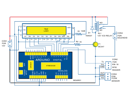
Circuit and working: -This project consists of sensor like analog flow sensor, Rfid reader, liquid crystal display, solenoid, arduino uno. The function of sensor and modules are following: -
1.Analog water flow sensor: -
This sensor measures the flow rate of fluid. It has two openings, one opening for in-take of fluid and other opening for out-take. you can say it is bi-directional.
It works on the principle of the Hall effect. The Hall effect is utilized in the flow meter using a small fan/propeller-shaped rotor, which is placed in the path of the liquid flowing.
2. RFID reader: -
EM018 RFID module is used to read the RFID tags.it decodes and transmit to controller via serial communication protocol
3.Liquid crystal display: -
LCD will display data which will received from controller (which is on arduino board). LCD configuration is alphanumeric (16*2).
4.Solenoid(12v): -
Solenoid allow fluid to flow. when it gets energized it open and allow fluid to flow otherwise it stay close and don’t allow fluid to flow across it.
Working: -
It is built around arduino uno development board, analog flow sensor, 16*2 alphanumeric LCD, 10k preset switch. Here Arduino Nano is a brain which process whole process.
1. Analog flow sensor contain three wires, out of these three wires one give output remaining two is given as power (5v and ground as per color specification, red for voltage and black for ground).
The liquid pushes against the fins of the rotor, causing it to rotate. The shaft of the rotor is connected to a Hall effect sensor. It is an arrangement of a current flowing coil and a magnet connected to the shaft of the rotor, thus a voltage/pulse is induced as this rotor rotates. In this flow meter, for every liter of liquid passing through it per minute, its outputs about 4.5 pulses.
Output pin of this sensor is connected to digital pin number 2, when liquid flow across it, gives out pulse is counted or measured by microcontroller and total number of received pulses is converted into specific unit like ml/second or liters/minute. This is due to the changing magnetic field caused by the magnet attached to the rotor shaft as seen in the picture below. We measure the number of pulses using an Arduino and then calculate the flow rate in liters per hour (L/hr.) using a simple conversion formula.
2.EM018 readerTx pin is connected to arduino microcontroller pin number 0(Rx pin which receive signal). when Rfid tags swipe across Reader em018 send data to MCU, if it matched then it sends signal to input pin of relay it gets energized it passes the 12v to solenoid via N/O pin of relay. At same time, LCD will display “put your vessel” on first line.
While solenoid get energized via relay, it allow the liquid from source to flow. solenoid is connected to flow sensor; flow sensor gets a liquid from solenoid and pass it via pushing a fan which is inside it. At same time, LCD will display amount of liquid on second line.
When a defined amount (mentioned in sketch) of liquid passed through flow sensor then relay get deenergized and solenoid don’t allow liquid to flow. At same time, LCD will display “remove your vessel " on first line.
If user want same amount of liquid, he/she should swipe card again across Rfid reader.
SoftwareThe software code is written in the Arduino programming language. Arduino IDE is used for compiling and uploading the sketch to ATmega328 microcontroller of the Arduino board. Every RFID tag has a unique number. This number has to be included in the Arduino code/sketch.
Arduino code uses LiquidCrystal.h header file for the LCD and serial communication for reading the data from the RFID reader. Two built-in functions are used namely, Serial.available( ) to return the RFID tag number arrived in the serial buffer and Serial.readString( ) to read a string of RFID tag numbers.
In this code/sketch, we used a variable as ‘int amount=1000’. This gives a default liquid amount of 1000 milliliter or one liter per card swipe. Just change the amount value as per your requirement.
Construction and testing1. Connect all the components and modules as per the schematic diagram.
2. Connect a 12V power supply from 12V adaptor or 12V battery to Vin pin of Arduino, relay driver and to relay NO pin.
3. Connect relay common pin to the solenoid as shown in the circuit diagram.
4. Check the default amount of liquid in the code for dispensing per minute.
5. Swipe the RFID tag over EM18 reader. If it matches the programmed RFID tag code, relay and solenoid will be energized, water from the source(tap) will flow through flow sensor.
6. You will get all relevant information on the LCD1 as already explained. Make sure that there is sufficient amount of liquid in the source (water tap or container). Less amount of liquid in the source means less pressure in liquid flow in the pipe, resulting in inaccuracy in the liquid flow measurement.


Comments