

Hardware components | ||||||
 |
| × | 1 | |||
| × | 3 | ||||
 |
| × | 2 | |||
|
| × | 1 | |||
| × | 1 | ||||
Software apps and online services | ||||||
 |
| |||||
Hand tools and fabrication machines | ||||||
 |
| |||||
In this series, I show how to replicate, visualize, and expand basic digital circuits using modern microcontroller technology. The goal is to make classic digital logic (AND, OR, NOT, flip-flops, clock generators, etc.) understandable using Arduino as a transparent experimentation tool.
Why does this project exist?Many beginners learn Arduino only through ready-made sample codes. The basics of digital logic are often lost in the process. At the same time, classic digital technology kits seem old-fashioned or expensive.
That's why I combine both: basic digital circuits + Arduino + visualization.
This allows learners to understand what is really happening.
What am I doing?I recreate a digital function in each part and explain:
- how the logic behind it works
- how to test it with simple Arduino examples
- how to make signals visible (LEDs, serial plotter, oscilloscope simulation)
Let's start.
-----------------------------------------------------------------------------------------------------------------
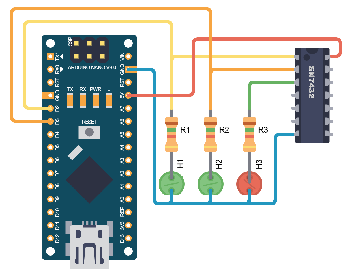
1. The Circuit SN7432The SN7432 is a quad OR device. The pin assignment of the device can be found in the following picture.
We will connect the two output pins of D2 and D3 to inputs 1A and 1B of the SN7432 and to an LED each so that we can better track the input signals. Output 1Y of the SN7432 is connected to a low-current LED via a 1.5 k resistor.
2. Arduino Sketch// Arduino and Logic circuit SN7432 (SN7400, SN7408 etc.)
const int OUT_PIN_A = 2;
const int OUT_PIN_B = 3;
void setup() {
//Outputs
pinMode(OUT_PIN_A, OUTPUT);
pinMode(OUT_PIN_B, OUTPUT);
}
void loop() {
digitalWrite(OUT_PIN_A, LOW);
digitalWrite(OUT_PIN_B, LOW);
delay(1000);
digitalWrite(OUT_PIN_A, HIGH);
digitalWrite(OUT_PIN_B, LOW);
delay(1000);
digitalWrite(OUT_PIN_A, LOW);
digitalWrite(OUT_PIN_B, HIGH);
delay(1000);
digitalWrite(OUT_PIN_A, HIGH);
digitalWrite(OUT_PIN_B, HIGH);
delay(1000);
}If either one of the two outputs D2 or D3 is switched to HIGH, the red LED at output 1Y lights up. If both outputs D2 and D3 are switched to LOW, the red LED at output 1Y goes out. The Arduino switches its outputs D2 and D3 according to the adjacent truth table.
- Use LEDs with suitable resistors.
- Pay attention to the polarity of the LEDs.
- Connect additional inputs and outputs.
- Implement a display or seven-segment display to show the input and output states.
- Send the input and output signals via the serial interface.
For more information, please visit my Blog:


Comments