

Hardware components | ||||||
 |
| × | 1 | |||
 |
| × | 2 | |||
 |
| × | 2 | |||
| × | 1 | ||||
 |
| × | 1 | |||
Software apps and online services | ||||||
 |
| |||||
Hand tools and fabrication machines | ||||||
 |
| |||||
In this series, I show how to replicate, visualize, and expand basic digital circuits using modern microcontroller technology. The goal is to make classic digital logic (AND, OR, NOT, flip-flops, clock generators, etc.) understandable using Arduino as a transparent experimentation tool.
Why does this project exist?Many beginners learn Arduino only through ready-made sample codes. The basics of digital logic are often lost in the process. At the same time, classic digital technology kits seem old-fashioned or expensive.
That's why I combine both: basic digital circuits + Arduino + visualization.
This allows learners to understand what is really happening.
What am I doing?I recreate a digital function in each part and explain:
- how the logic behind it works
- how to test it with simple Arduino examples
- how to make signals visible (LEDs, serial plotter, oscilloscope simulation)
Let's start.
-----------------------------------------------------------------------------------------------------------------
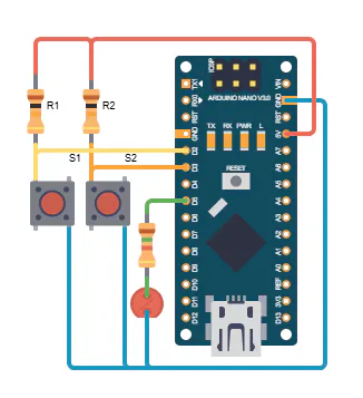
1. The ideaI admit, it is tedious to have to write separate software for each logic link. So why not send the desired link from the PC to the Arduino and let it do the rest? In the following program, the Arduino continuously reads the two inputs D2 and D3. The Arduino logically links the two input signals and outputs the result at output D5. The user can send the desired digital link to the Arduino via the Arduino terminal program.
2. Arduino Sketch//Arduino as a universal logic module
const int IN_PIN_A = 2;
const int IN_PIN_B = 3;
const int OUT_PIN_Q = 5;
int command = 'U';
void setup() {
// Initialize serial port
Serial.begin(19200);
ShowBehaviour();
//Inputs
pinMode(IN_PIN_A, INPUT);
pinMode(IN_PIN_B, INPUT);
//Output
pinMode(OUT_PIN_Q, OUTPUT);
}
void loop() {
bool q = false;
bool a = digitalRead(IN_PIN_A) == LOW;
bool b = digitalRead(IN_PIN_B) == LOW;
int ret;
if (Serial.available() > 0) {
command = Serial.read(); // Save character received.
ret = Serial.read(); // Save character received <return>.
command &= ~0x20; //Kleinbuchstaben in Grossbuchstaben ändern
ShowBehaviour();
}
switch(command) {
case 'U': { //UND
q = a && b;
}
break;
case 'O': { //ODER
q = a || b;
}
break;
case 'A': { //NAND
q = !(a && b);
}
break;
case 'N': { //NOR
q = !(a || b);
}
break;
case 'E': { //XOR
q = a ^ b;
}
break;
case 'X': { //XNOR
q = !(a ^ b);
}
break;
}
Serial.print("A: ");
Serial.print(a);
Serial.println();
Serial.print("B: ");
Serial.print(b);
Serial.println();
Serial.print("Q: ");
Serial.print(q);
Serial.print("\n-----\n");
digitalWrite(OUT_PIN_Q, q ? HIGH : LOW);
delay(500);
}
void ShowBehaviour(void) {
switch(command)
{
case 'U': { //UND
Serial.print("Arduino works as an AND.\n");
}
break;
case 'O': { //ODER
Serial.print("Arduino works as an OR.\n");
}
break;
case 'A': { //NAND
Serial.print("Arduino works as a NAND.\n");
}
break;
case 'N': { //NOR
Serial.print("Arduino works as a NOR.\n");
}
break;
case 'E': {//XOR
Serial.print("Arduino works as a XOR.\n");
}
break;
case 'X': { //XNOR
Serial.print("Arduino works as a XNOR.\n");
}
break;
}
}The commands for linking sent via the terminal program are as follows:
- u, U: AND link
- o, O: OR link
- e, E: Exclusive OR lin
- a, A: NAND link
- n, N: NOR link
- x, X: Exclusive NOT OR link
The output of the terminal program looks like this for our AND gate, for example:
Arduino works as an AND
A: 0 B: 0 => Q: 0
A: 1 B: 0 => Q: 0
A: 0 B: 1 => Q: 0
A: 1 B: 1 => Q: 1- Don't forget pull-up resistors.
- Use LEDs with suitable resistors.
- Connect switches correctly.
- Pay attention to the polarity of the LEDs.
- Connect additional inputs and outputs.
- Implement an additional display or seven-segment display to show the input and output signals.
For more information, please visit my Blog:


Comments