

Hardware components | ||||||
 |
| × | 1 | |||
| × | 1 | ||||
 |
| × | 1 | |||
 |
| × | 2 | |||
Software apps and online services | ||||||
 |
| |||||
Hand tools and fabrication machines | ||||||
 |
| |||||
In this series, I show how to replicate, visualize, and expand basic digital circuits using modern microcontroller technology. The goal is to make classic digital logic (AND, OR, NOT, flip-flops, clock generators, etc.) understandable using Arduino as a transparent experimentation tool.
Why does this project exist?Many beginners learn Arduino only through ready-made sample codes. The basics of digital logic are often lost in the process. At the same time, classic digital technology kits seem old-fashioned or expensive.
That's why I combine both: basic digital circuits + Arduino + visualization.
This allows learners to understand what is really happening.
What am I doing?I recreate a digital function in each part and explain:
- how the logic behind it works
- how to test it with simple Arduino examples
- how to make signals visible (LEDs, serial plotter, oscilloscope simulation)
Let's start.
-----------------------------------------------------------------------------------------------------------------
1. What is a digital signal?A digital signal has only two defined states:
- HIGH (1) – typically 5V or 3.3V on the Arduino
- LOW (0) – 0V
The output of a NAND gate goes LOW when both inputs are HIGH.
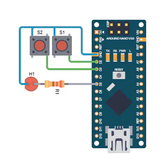
The logic circuit
The Truth Table
The two input pins D2 and D3 are connected to the internal pull-up resistors with +5 V. Using switches S1 and S2, the inputs can be switched independently of each other to ground (LOW). The Arduino continuously reads the states of its inputs, inverts them, links them logically, and outputs the result via pin D5.
The LED at output D5 lights up when the two inputs D2 and D3 have the signal “LOW” or different signals.
3. Arduino Sketch// Arduino simulates a NAND gate
const int IN_PIN_A = 2;
const int IN_PIN_B = 3;
const int OUT_PIN_Q = 5;
void setup() {
//Inputs
pinMode(IN_PIN_A, INPUT);
pinMode(IN_PIN_B, INPUT);
//Outputs
pinMode(OUT_PIN_Q, OUTPUT);
}
void loop() {
bool a, b, q;
a = digitalRead(IN_PIN_A) == LOW; //Read inputs
b = digitalRead(IN_PIN_B) == LOW;
q = !(a && b); //Link signals
digitalWrite(OUT_PIN_Q, q ? HIGH : LOW);
}- Use LEDs with suitable resistors.
- Connect switches correctly.
- Pay attention to the polarity of the light-emitting diode.
- Wire additional inputs and outputs.
- Display for showing input and output signals. In this series, I show how to replicate, visualize, and expand basic digital circuits using modern microcontroller technology. The goal is to make classic digital logic (AND, OR, NOT, flip-flops, clock generators, etc.) understandable using Arduino as a transparent experimentation tool.
For more information, please visit my Blog:


Comments