

Hardware components | ||||||
 |
| × | 1 | |||
| × | 1 | ||||
 |
| × | 1 | |||
| × | 1 | ||||
| × | 1 | ||||
Software apps and online services | ||||||
| ||||||
 |
| |||||
Hand tools and fabrication machines | ||||||
 |
| |||||
There are copious amounts of wireless BBQ/oven thermometers available via retail. So why do another? Actually, this project started when I went looking for a BBQ meat thermometer that would handle 4 separate cuts of meat and would allow me to monitor the temperature from inside the house and in the back yard. My search came up empty, as all the products had at least one fatal flaw:
- Units that had a smartphone app generally had unfavorable user reviews
- Finding more than 2 probes was a difficult and/or expensive
- Remote monitoring required carrying the receiver around with me (and remembering to take it with me as I walked around)
So I pivoted and instead looked at this as a way to shake out the Blynk app that I had backed on Kickstarter, as well as using an ESP-12E/F as the MCU as well as the WiFi adapter. As usual, this would be a "soup to nuts" project that included software, hardware, and 3D design and printing of the enclosure. There was enough circuitry involved that I would design a PCB and have it fabricated.
My project goals were to be able to monitor the temperature of 4 cuts of meat on my iPhone. This would allow me to spend more time with family/guests instead of hovering over the BBQ. Also, push notifications when each cut of meat is done would ensure each was cooked to perfection.
WMT4 Features
- 4 separate probes that can be left in the BBQ during the entire cooking process (700 degrees F tolerance)
- control unit with an LCD display of each temp and setpoint, plus a "done" indicator
- iPhone/Android app with controls and displays for each probe
- WiFi communication
Control Module
- ESP12-E/F MCU/WiFi using an Adafruit Huzzah module
- Custom PCB with a 4-port 12-bit ADC, opamps, probe RC circuitry, 3.3V and 5V power rails, and 3.3/5V level-shifters
- 20x4 LCD display (I2C connection)
- Custom 3D-printed enclosure
- Maverick ET-73 thermistor probes
Firmware
- Arduino sketch (developed using IDE 1.6.8 and ESP8266 library version 2.2.0)
- MCP320x library (my library for the MCP3204/8 12-bit ADC)
Blynk App
- Slider to set target temperature
- Display of current temperature
- LED to indicate probe is present
- LED to indicate setpoint reached
- A "clone" button to copy the settings from the first probe to the others
- A graph of the temperature change over time (one line per probe, color coded)
- Push notifications when each probe has reached its setpoint
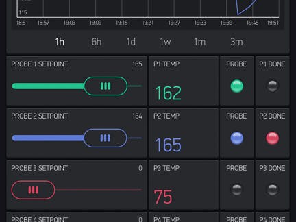
One of the most significant benefits of the WMT4 is the temperature history graph. Most BBQ grills have hot and cool spots, so this allows you to see how fast each cut is cooking and adjust the placement as necessary. I usually get each cut to within a degree or two of the target with all the cuts finished at the same time by carefully watching this graph.
(Note: in the photo above, the initial temperature spikes on the history graph are due to the probes extending all the way through the chicken breast and contacting the BBQ grate.)
DesignTheory and Concept
There are a number of useful references for thermistor projects that were very helpful in designing this project. By far the most useful was the Adafruit Cloud Thermometer by Tony DiCola. This tutorial introduced me to the Steinhart-Hart equation for thermistors, which is the core algorithm used in this project. If you decide to use different thermistor probes, you should follow the section on probe calibration and replace the A, B, and C Steinhart-Hart coefficients in the sketch. A different probe may also have a different resistance so you may also need to change the probe series resistor in the circuit and sketch. Tony's algorithm for determining the probe voltage elegantly uses the resistance ratio, which eliminates the need to know the reference voltage. Thus, if you decide to use an MCU that runs at 5V this algorithm does not need to be modified.
The basic approach to temperature measurement is simple: determine the resistance of each probe and use the Steinhart-Hart algorithm to calculate the temperature. (A thermistor's resistance varies with temperature.) By using a probe with a very high maximum temperature (700 degrees F in this case) we can leave the probe in the BBQ/oven for the full duration of the cooking cycle.
The Blynk app manages all of the values: sets the target temperature, displays the current temperature, and graphs the temperature over time. It also has the state info: which probes are inserted plus a setpoint indicator. In addition, there is an LCD on the control module that displays the temperatures (current and set) as well as setpoint indicator. This allows the WMT4 to be used without the Blynk app or just to quickly check the temperature without having to refer to the app.
Hardware
Using the ESP8266 brings two significant upsides: WiFi is incredibly easy to use with Blynk and the ESP8266 WiFi libraries, plus generous SRAM.
An attempt at using an Uno for the MCU with the ESP8266 (ESP-01) as the Wifi adapter ended in grief, as the memory requirements from the Blynk and WiFi libraries resulted in memory corruption when the stack and heap collided. No such issues using the ESP as the MCU as well, plus the built-in WiFi is far easier to deal with than an offboard ESP-01 (no dealing with the UART TX/RX lines, AT command set, etc.)
One downside of using the ESP8266 as the MCU is its single analog port. Since we need 4 ports, I chose to use a Microchip MCP3204 12-bit ADC that communicates with the ESP8266 using SPI.
Two consequences of this decision were that I would need to convert the (very) high impedance thermistor input to low impedance by using opamps in a linear 1:1 configuration as well as locating an MCP3204 library. I managed to find a old library for the device, but it needed to be updated for the current Arduino IDE and was in need of a code cleanup.
I decided to use this as a reason to rewrite the library from scratch and publish my first Arduino library as an exercise. You can find the library here.
The voltage regulator supplies 5V to the ESP, and the Huzzah's on-board 3.3V regulator supplies the 3.3V power rail. This works because the current demands from the probes and MCP are slight.
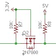
The opamps run on 5V as well as the LCD, and bi-directional MOSFET-based level shifters are provided for the I2C communication path to the LCD.
All this circuitry also meant designing and fabbing a PCB.
See the Bill of Materials for specifics on the parts including the cost and a link for purchasing.
Note: My remaining stock of PCB boards has been sold, but you can purchase one from PCBs.io.
Software
The biggest challenge I had with the sketch was the volume of data that had to be synchronized through the Blynk app. At first, I was overwhelming the Blynk server and was suffering a lot of timeouts. And once it started, it just got progressively worse. The solution was to minimize the amount of data that had to be exchanged between the sketch and the Blynk dashboard. Another key stability strategy was breaking the work up into small modules and scheduling them through the timer in such a way as to not overlap each other (much, anyway). Blynk also seems to be sensitive to the order in which things start.
I have found that you must start the Blynk app before the control unit for the most stability. A reminder of this is displayed when the control unit boots.
Enclosure
The enclosure was designed in Sketchup.
There are separate files for the base and lid. Both have standoffs to support the main PCB and the 20x4 LCD, respectively. The enclosure is relatively tall to allow some space above the voltage regulator so that things don't overheat when the unit is on for long periods of time.
The 2.5mm jack mounting holes are recessed to ensure there is sufficient barrel length available to firmly attach the nut on the exterior.
You should not need to modify the enclosure to fit the jacks or the power switch if you use the ones specified in the BOM.
ImplementationRepository Contents
- STL files for the enclosure base and lid, Cura profile
- BOM, Eagle 7 files (schematic, board, connections, device library)
- Photos of the Blynk dashboard, controller exterior, controller interior
- Arduino sketch, Blynk dashboard QR code
See the full open source repository for more details as well as hints for how you can implement this for yourself.
Copyright Notice
Copyright 2016 Rob Redford
This work is licensed under the Creative Commons Attribution-NonCommercial-ShareAlike 4.0 International License.
To view a copy of this license, visit BY-NC-SA.


Comments