What would a person do without a garage, workbench, and a bunch of computer parts to tinker with? Anyone can purchase home automation systems now days but it is way more fun to build your own from scratch! We all know how good it feels when you can combine some components like resistors, transistors, and relays and make something happen. It was in this true "maker" spirit, that I decided to figure out a way to automate my garage door opener by controlling it with my Windows 10 phone via Bluetooth.
This project will show you how to build a circuit that will talk to an Arduino via Bluetooth radio using my Windows 10 Universal C# project. The app is designed to send a signal to a Bluetooth module which in turn energizes a small relay. The relay then sends a short signal to your garage door opener. Basically, we are simulating the process of pressing the actuator switch on the wall in the garage by using the new Windows Arduino Remote Library.
Once installed, this library allows us to communicate with Arduino without creating a sketch! That's right. Once a file called "standardfirmata" is uploaded to the Arduino, you can write code in Visual Studio that can access all of the Arduino features directly.
By the way, if you want to create one of these apps from scratch, open a new Universal project and go to Tools | Nuget Manager for this solution and search for Arduino Remote. Once it locates it, install it so you will have access to all the tools/libraries you need.
Then, use the "standardfirmata" file included in this project and upload it to an Arduino. I changed the baud rate (communication speed) on this file to match the Bluetooth module I purchased from Sparkfun (see parts list). The rest of the file is original.
Getting Started- From the parts list, get your Arduino and Bluetooth module, a small breadboard, and the other components I listed.
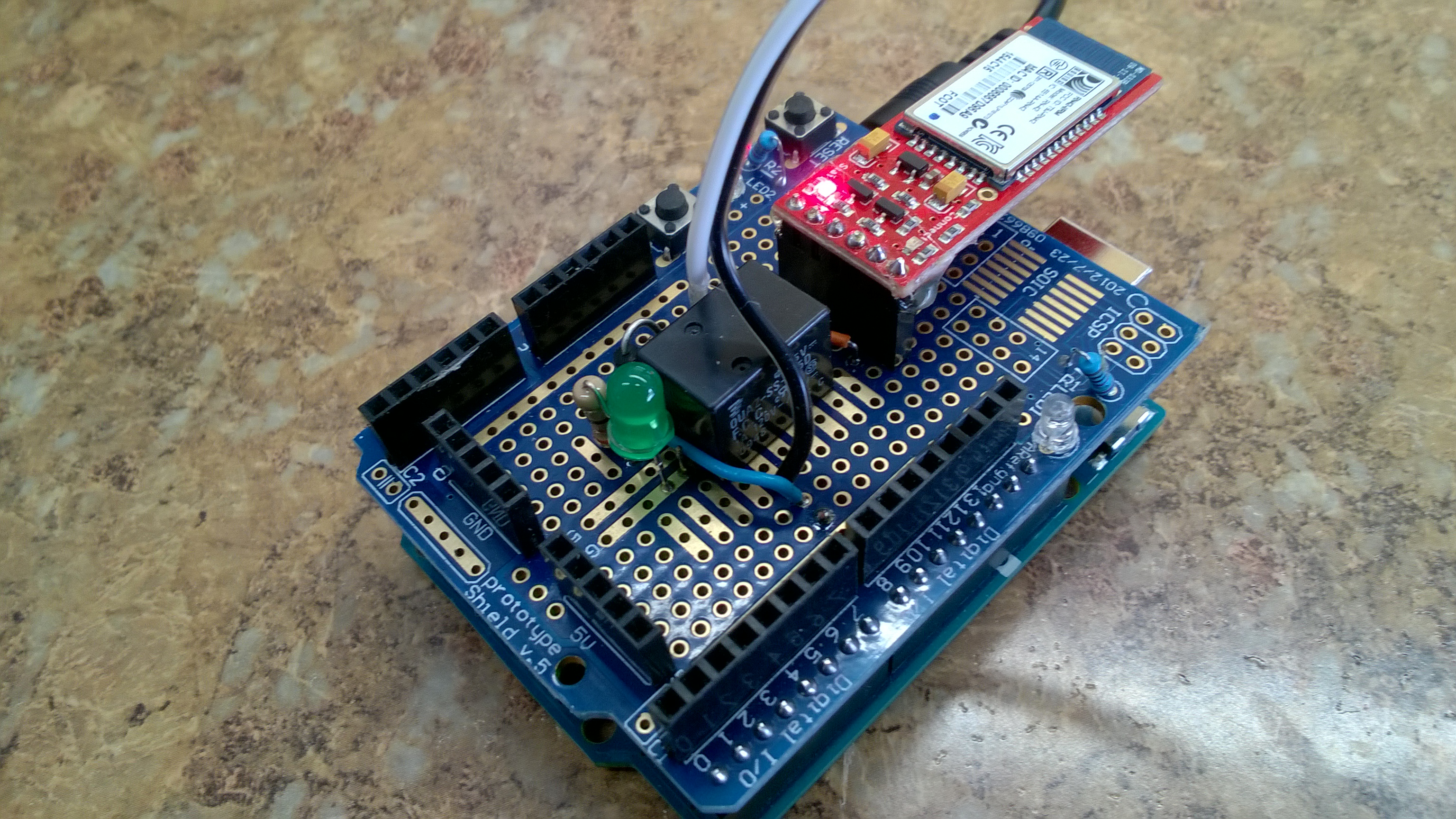
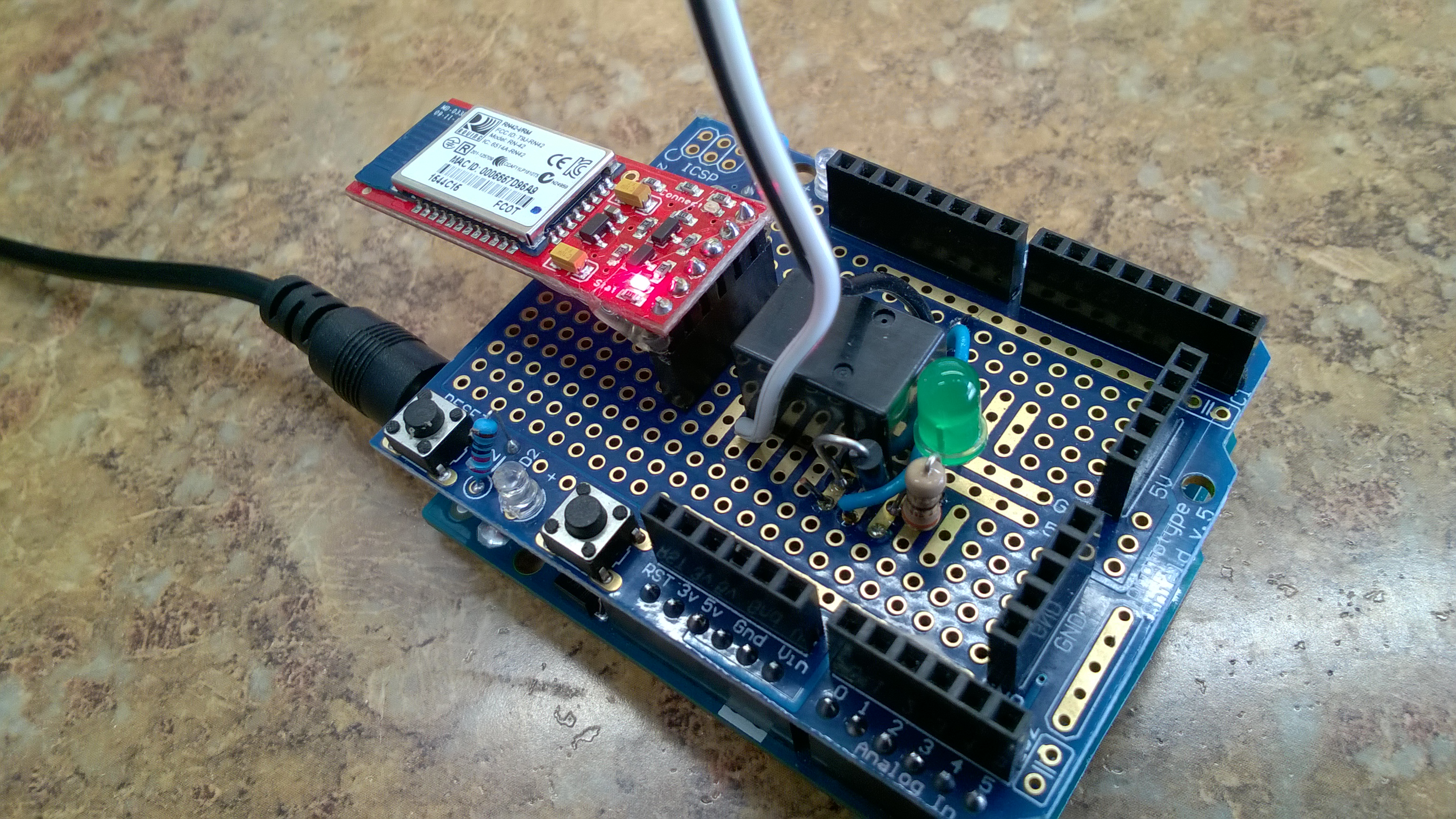
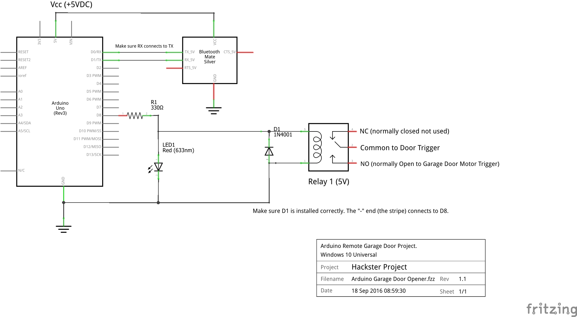
Note: You can use any 5VDC relay and I listed a couple. Make sure to wire it carefully because each manufacturer uses a different pinout layout. You will only use the NO(normally open) and Common pins for this project. And please make sure to install the diode correctly. The end of the diode with the band is called the Cathode and it is the negative end. The opposite end is called the Anode and is the positive end. However, in the application, the negative (cathode) is connected to the Arduino and the Anode (+) end is connected to ground. This sounds backwards I know but we are using the diode as a "blocking" or "snubber" diode so it is "reversed-biased". This just means it is wired backwards. If you have never worked with relays, check out my video here.
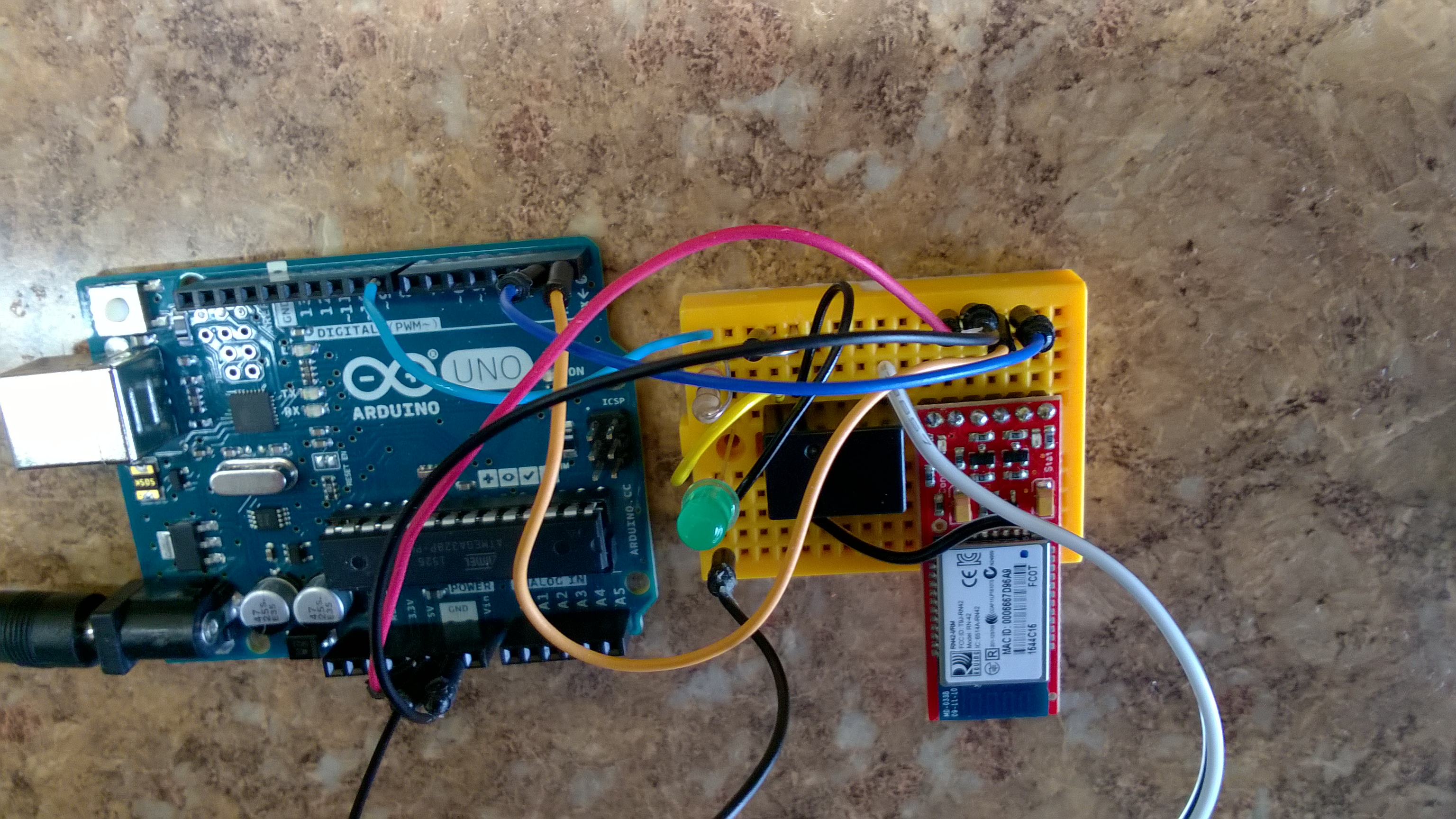
- I used a small breadboard to initially create the project. I soldered all the parts onto a shield after I was sure it was all working.
- Download the VS project to your desktop and unzip it.
- Look at the "Readme" file to see how to prepare the Arduino.
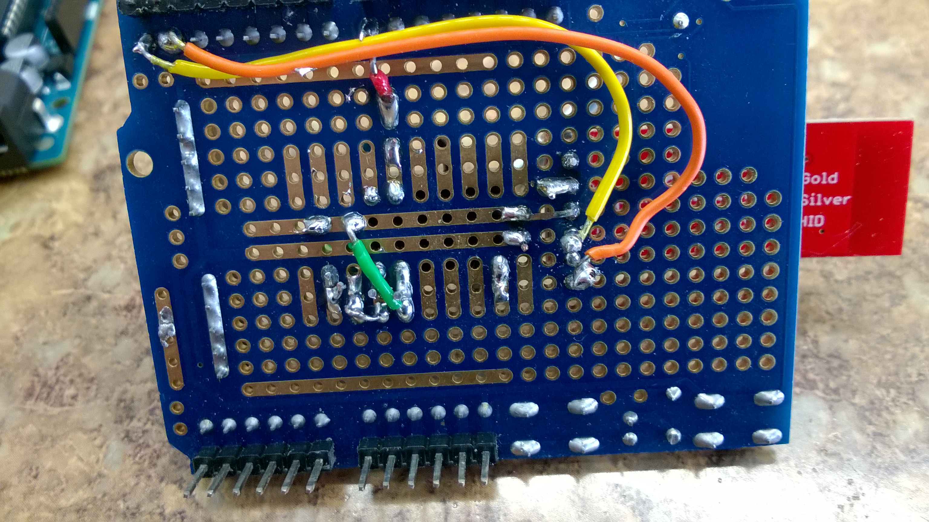
- Build the circuit by referring to my schematic and the included images.
- You need to run two wires from the terminals on the back of the opener where the wall switch is connected. Follow the two small wires coming from the wall switch when the opener was installed. Add a wire to each of the terminals and connect them to the relay on your breadboard. In my schematic, I refer to these as the "trigger wires". Leave the original wires in place so your wall switch still operates.
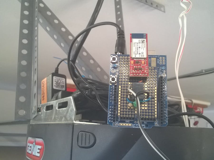
- I then carefully placed my entire Arduino and circuit board on top of the garage opener as shown in my cover image. I ran a wall wart to the Arduino to give it power.
Bluetooth Setup- When you are ready to pair your Bluetooth module to the computer, power up your circuit and open the notifications menu on the Windows 10 taskbar and choose Bluetooth | Show devices.
- You should see your Bluetooth module listed. Mine started with RNBT. Write this down because you will need to insert it in the code later.
- Now it is time to try the code.
Run the Included Application- Now you are ready to try my app. Since it is a Universal C# project, you can run it on any Windows 10 computer or other device.
- Open the project in VS and navigate to the Mainpage.Xaml.cs code page. Use my comments to find the line where you insert the actual ID of your Bluetooth module you paired with your phone/computer.
- Now clean the project (View | Clean) and then rebuild it (View |Rebuild) to start clean and to test for errors.
- Now run the app. You will see a splash screen then the main page will display. When you are connected to your BT module, there will be a message box that prompts you to begin. If the BT connection fails, exit the app and restart. In my garage I only have about a 25 foot range when the circuit board is sitting inside the opener mechanism.
- MAKE SURE THERE ARE NO OBSTACLES BEFORE TESTING!
- When connected, the big button on screen is enabled and you can click it to activate the opener. The app sends a 1 second pulse to the opener. This simulates pressing the original switch that was installed with the opener.


_ztBMuBhMHo.jpg?auto=compress%2Cformat&w=48&h=48&fit=fill&bg=ffffff)


_3u05Tpwasz.png?auto=compress%2Cformat&w=40&h=40&fit=fillmax&bg=fff&dpr=2)
Comments