

Hardware components | ||||||
 |
| × | 1 | |||
| × | 3 | ||||
| × | 2 | ||||
| × | 1 | ||||
| × | 1 | ||||
| × | 3 | ||||
Software apps and online services | ||||||
| ||||||
| ||||||
| ||||||
| ||||||
| ||||||
Hand tools and fabrication machines | ||||||
| ||||||
 |
| |||||
| ||||||
Radio Frequency (RF) Energy is all around us. There is a LOT of money in industry behind the RF devices that are filling our lives. RF has been added to home utility meters, never mind the myriads of cell phones, WiFi devices, appliance remotes, car remotes, .. the list is just growing....
There are some studies out there indicating all this RF may have biological effects. Some people are traveling cross country to the town in the USA where radio frequency energy free-zones have been established!
People being attacked by RF Energy!
Wouldn't it be revealing to have glasses to see all this energy floating around us? What devices in our homes are putting out this energy? When are they transmitting? What frequency is the radiation?
The Hexiwear platform with the myriad of Click boards offers a rapid prototyping of any concept. This project uses the RF Click modules in the HexiWear docking station to produce a sensing platform to reveal the Radio Frequency (RF) energy around us.
The ProjectEven though it would be great to use the built-In Hexiwear Blue Tooth connection to monitor this platform to your smart phone, we can't, as all this is an example of the RF energy we are talking about!
During this project, it was also discovered that the RF Clicks must be read as rapidly as possible, as many RF sources have short transmissions that if the code is busy doing something else, like updating displays, you missed the brief presence of RF energy!
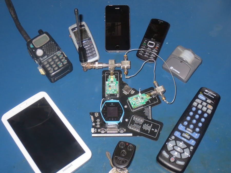
The platform consists of:
1. Hexiwear in the docking station with with two RF Click modules
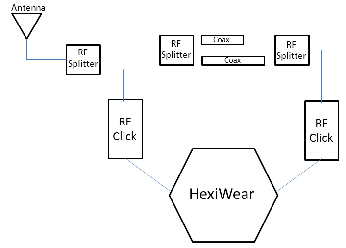
2. An antenna, that is connected to an RF splitter
3. Two RF splitters that are combined using unequal cable lengths
4. Optionally: We added a beeper wired in place of the internal Vibro motor to alarm for High RF energy levels
Th RF Click module converts RF energy into an ADC word value over the broad frequency band of 1 MHz to 8 GHz.
See this link for an overview of the RF Spectrum
The first RF splitter splits the energy captured by the antenna to one RF click module. This module measures the power present. The user can set a threshold at which an alarm (Red LED) occurs.
The other half of the first splitter goes to another pair of splitters that recombine the signal again after is has traveled across two different paths. The unequal paths create a phase difference that creates a cancellation pattern, imparting an amplitude difference Vs frequency. This pattern is used in a look up table to estimate the frequency of the RF energy. If the frequency is between 700 MHz and 1.4 GHz, an estimate is provided to the user.
Different path differences will create different RF responses Vs frequency. A third channel could be added to cover a larger band, or a different path difference between the two coaxes could be used to move the optimal frequency detection coverage to a different part of the spectrum.
Operational UsePower up system. The threshold for alarm can be set by pressing buttons T1 and T2 on the docking station. Note the alarm may still beep even though the display indicated power is still below the threshold. This is because the displayed power is an average value, and many of the RF signals are short duration. The RF Monitor captures these short duration pulses and sounds the alarm.
The HexiWear LED will glow red if it has detected energy above the threshold set by the buttons. It glows green when the levels are above the system noise floor, but not large enough to trigger a major (Red) alarm.
The serial monitor also shows the min/max/average ADC counts from the sensors.
The display and serial port are only updates every few seconds, as we discovered much of the RF environment consists of short pulses, so the HexiWear must spend its time reading the ADC's as any other activities risk missing the RF energy.
Beeper Instead of Vibro MotorThe RF environment is so congested, that the vibro motor was vibrating the Hexiwear off the docking station, so we modified the Hexiwear to have a beeper sound instead of the vibrating motor. Just detach one of the motor leads and solder the beeper indicator in the parts list in its place. See photo below:
There were several key hurdles during software development:
1) We used mBed.org compiler, as the FreeRTos was something we would have needed more time to become familiar with
2) Also found the spi.frequency() command would not change the clock rate on the SPI lines. Not sure if this was a bug or something we were doing wrong, but the RF Click can't be read much faster than 100KS/s, and we measured teh Hexiwear clock on the SPI line at over 15 MHz, and it would not change withissuing different spi.frequency() commands. This resulted in ocassionally WRONG readings from the RF Click modules. Therefore, we wrote a bit-bang version of the SPI code, so the timing could be compliant.
3) Updating the display takes a lot of time away from reading the RF Click Modules, and we discovered modern RF devices are communicating in short pulses. If you aren't reading them constantly, you miss these bursts. Therefore, the main loop must be kept lean, dominating the time reading the modules. We therefore only update the displays only every few seconds. The alarms and LED warnings happen immediately, however.
4) On power up, we discovered the RF environment is FULL of energy. We needed to add a user adjustable threshold to ignore below some threshold, otherwise the unit would ring continuously!
Testing with Various RF DevicesBelow is a video, testing the system with various RF devices. It's amazing how much a WiFi routers and phone put out into the environment. The phones even transmit when they are turning off!
EnclosureThe RF Splitters can be replaced by three resistors, so conceptually the HexiWear main body could be mounted on a board in a smaller form factor than the Docking Station. This board would have the RF splitters and RF Click Boards(or the integrated circuits soldered directly to the board) integrating the concept in a sleek form factor. An antenna is needed as well. This was sketched in Fusion 360 to illustrate the concept.
Custom Package
Add a 3rd channel for better frequency estimation
An a low noise amplifier to the antenna to make it even more sensitive.


Comments