


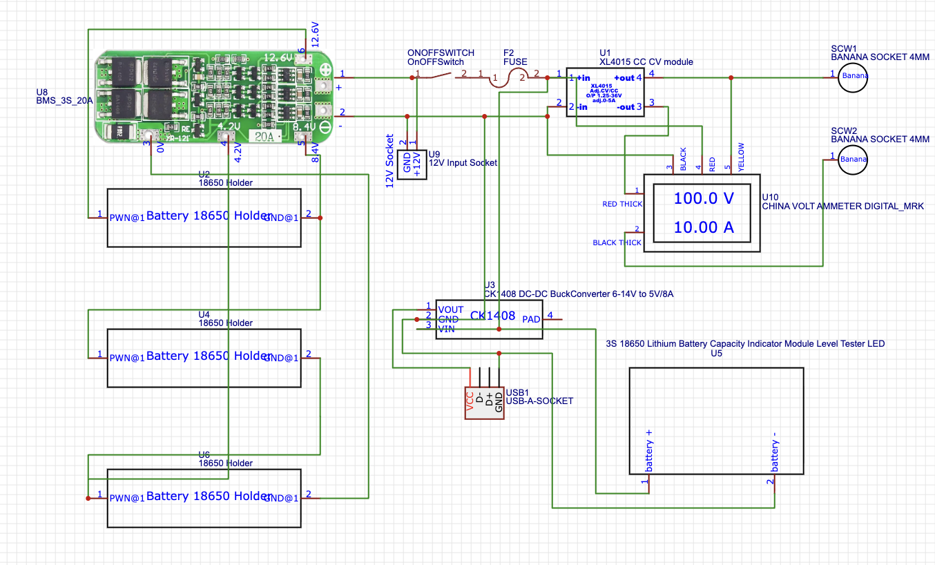
Design a PCB in EasyEDA for your portable adjustable power supply with USB output. Include connections for:
- XL4015 module
- 3S battery holder & BMS
- DC volt-amp meter
- Banana & USB sockets
- Fuse & DC 12V jack
- On/off switch & multiturn potentiometer
Attach the schematic diagram for reference. Once done, export the Gerber files and order your PCB easily through PCBWay.
Tip: Keep traces for high-current paths thick and clear for safe operation.Step 2: Installing Output Sockets & DC Volt-Amp Meter
Insert Banana Sockets and USB Socket
- Mount the banana socket pair (for adjustable voltage output) and the USB socket (for mobile charging) onto the PCB or enclosure.
- Make sure they are securely fixed for safe use.
- Prepare DC Volt-Amp Meter
- On the back of the DC volt-amp meter, remove the plastic connector block carefully.
- This exposes the terminals so you can directly solder wires to the PCB.
- Connect to PCB
- Solder the volt and amp input wires from the meter to the corresponding output points on your PCB.
- Double-check polarity and connections: Voltage+ to output+, Voltage– to output–, Current+ and Current– to current path.
- Insert XL4015 Module
- Place the XL4015 buck module on the PCB or securely inside the enclosure.
- Align its input and output terminals with your PCB connections for smooth soldering.
- Install Fuse & Fuse Box
- Mount the fuse holder/box near the input line to protect your circuit.
- Insert the correct fuse (rated for your system current, e.g., 5–10A).
- Mount DC 12V Input Socket
- Fix the DC input jack on the enclosure.
- Connect it to the PCB input via the fuse box so the power from batteries or adapter goes through the fuse before reaching the XL4015 module.
Tip: Keep all wires short and secure, and double-check polarity before powering on.
Step 4: Installing Battery Holder, 3S Level Indicator & On/Off Switch- Insert 3×18650 Battery Holder
- Mount the 18650 battery holder securely inside the enclosure.
- Make sure the holder aligns with the PCB connections for 12V output through the XL4015 module.
- Install 3S Battery Level Indicator
- Choose a small type 3S Li-ion battery indicator.
- Connect it to the battery terminals to monitor the charge level of your 3×18650 pack.
- Mount On/Off Switch
- Fix the on/off switch on the enclosure for convenient power control.
- Connect it in line with the input or output power path depending on whether you want to switch the whole system or just the output
- Solder All Legs
- Carefully solder all component legs (XL4015, sockets, volt-amp meter, BMS wires, potentiometer, switch, etc.) to the PCB.
- Make sure each solder joint is clean and strong to avoid loose connections.
- Secure Components from the Bottom
- Use bolts, nuts, and washers to fix components like sockets
- Tighten carefully using a spanner or pliers to ensure the components are stable but not stressed.
- Check All Connections
- Verify all connections and polarities before inserting batteries.
- Ensure no wires are touching each other to prevent short circuits.
Unleash your creativity and bring your 3D ideas to life! PCBWay invites all makers and designers to participate in two exciting categories:
- Eon-Themed Designs: Give PCBWay’s mascot, Eon, a fresh new look with your imagination — new outfits, poses, or expressions!
- Open Creative Designs: Design your own original 3D character, figurine, or collectible — from fantasy creatures to action figures.
Why participate?
- Win up to $500 cash, coupons, and certificates
- Have your design professionally 3D printed
- Get featured on PCBWay’s platform and show your talent to the community
How to enter:
Submit your 3D files (STL, STEP, or similar) through the PCBWay Open Source Community. You can enter one or both categories!
Deadline: November 10, 2025 — Don’t miss your chance to turn imagination into reality!
Click here to enter the contest!
Step 7: Mounting Components on PCB Bottom- Install DFRobot 12V→5V 8A Module
- Place the DFRobot step-down module on the bottom side of the PCB.
- Align its input/output pads with your PCB connections for proper soldering.
- Install 3S BMS Module
- Place the 3S Li-ion BMS also on the PCB bottom.
- Make sure the battery input and output lines match your PCB traces.
- Solder All Connection Points
- Carefully solder all pads for both the DFRobot module and BMS.
- Double-check polarity and trace alignment for safe operation.
- Clean the PCB
- Use PCB cleaning liquid (or isopropyl alcohol) and a small brush to remove flux residues and solder splashes.
- Gently brush all soldered areas, especially around the bottom-side SMD components like the DFRobot 12V→5V module and 3S BMS.
- Dry the PCB
- Allow the PCB to air-dry completely or use a soft cloth to remove excess liquid.
- Ensure no moisture remains before inserting batteries or powering up.
- Final Inspection
- Check for loose solder joints, short circuits, or stray wires.
- Once clean and inspected, your PCB is ready for assembly into the enclosure
- Insert the Multiturn Potentiometer
- Take your blue precision multiturn potentiometer.
- Place it into the hole on the PCB designed for it.
- Secure with Nut
- Tighten the potentiometer using the supplied nut from the top or bottom to ensure it doesn’t move.
- Solder External Wires
- Solder three wires from the potentiometer to the PCB points.
- Make sure the wires are secure and neat.
- Disconnect XL4015 Built-in Pot
- Before connecting, remove the inbuilt voltage adjust potentiometer from the XL4015 module.
- This ensures that the external precision pot will control the voltage without interference.
- Connect Wires to XL4015 Module
- Solder the three wires from the multiturn potentiometer to the voltage adjust points on the XL4015 module.
- Double-check connections and polarity to avoid misadjustment.
- Prepare Acrylic Sheets
- Use 3mm acrylic sheets for your enclosure.
- Measure and cut each piece according to the size of your assembled PCB and components.
- Use a Laser Cutter (Optional)
- If available, laser cut the acrylic pieces for precise edges and fitting.
- Make holes for banana sockets, USB socket, DC input, switch, volt-amp meter, and potentiometer.
- Assemble the Box
- Fit all acrylic pieces together to form a box shape around the PCB.
- Ensure openings align with all components for easy access.
- Glue the Pieces
- Use acrylic glue to secure all sides.
- Hold until the glue sets for a strong, neat enclosure.
- Fix the PCB in the Box
- Place the assembled PCB into the acrylic enclosure.
- Use glue or screws to secure it firmly in place.
- Insert Fuse into Fuse Box
- Place the correct rated fuse into the fuse holder.
- Make sure it’s secure and easily accessible for replacement if needed.
- Insert 3×18650 Batteries
- Use high-quality batteries of the same type and charge level.
- Insert them into the battery holder ensuring correct polarity.
- Close the Acrylic Top
- Use your laser-cut acrylic top with pre-made holes for sockets, switch, volt-amp meter, and potentiometer.
- Fit it carefully and glue or snap it in place.
Tip: Double-check all connections and make sure batteries are inserted correctly before powering on.Step 12: Fixing the Handle & Testing USB Output
- Attach the Handle
- Fix a portable handle on top of the acrylic enclosure using screws or glue.
- Make sure it’s stable and comfortable to carry.
- Initial USB Testing
- Switch ON
- Connect a mobile phone or any USB device to the USB output.
- Verify that it charges correctly and the volt-amp meter displays accurate readings.
5 More Images
- Connect Banana Test Leads
- Insert male banana connectors into the output banana sockets (+ and –).
- Make sure the polarity is correct: red to +, black to –.
- Adjust the Precision Potentiometer
- Use the blue multiturn potentiometer to adjust the output voltage.
- You can now fine-tune the voltage very precisely from 1V up to 12V.
- Check Current Handling
- The XL4015 module can supply high current (up to its rated limit, e.g., 5A).
- Use a load or device to verify that the system delivers both stable voltage and sufficient current.
- Monitor with Volt-Amp Meter
- Keep an eye on the DC volt-amp meter to ensure the voltage and current are within safe limits
- You can safely charge mobile devices, test electronics, and adjust voltage precisely with the multiturn potentiometer.
- Always observe polarity, current limits, and proper connections for safe operation.
- For a visual guide and demonstration, you can watch the YouTube video linked below for more detailed instructions.
- CLICK HERE

Comments