


I’m on a mission to reduce the amount of noise my LulzBot Mini 3D printer makes. I’ve already added a motor damper to the Y axis. However, one thing that is consistently noising is the case fan. It is on at > 70% nearly all the time. In addition to this, the air vent fins in the side of the case the fan is mounted to amplify the noise. So, I decided to build my own fan controller. Killing 2 birds with one stone, I also wanted to merge my LED light controller into this project.
Read the full write-up with source and links here.
Pretty straight forward. An Arduino Nano is at the heart of it. It monitors 2 temperature sensors – one on the power supply, and one near the stepper motor controllers on the RAMBO Mini board. The primary monitoring is the motor controller as these get hot. The power supply monitor is for info purposes. The Duino monitors the temperature inside the unit, and adjust the fan speed accordingly. It also has a button to allow me to set the LED to 3 different levels.
How well does it work?I’ve mounted the temperature sensors, the fan, connected power and have started further testing. Overall, I’m very happy with the result. The fan is quiet now and idles at about 600 RPM. Once the printer starts and the driver chips begin heating up, it ramps up to 1200 RPM. Even at this speed the fan is barely noticeable. The hum of the steppers stands out more now. Before I mounted the temp sensor, I used by laser temperature gun to monitor the status of the motor driver chips both during idle as well as printing. Given the X & Y motors do a lot more work, I focused on those 2 chips. At idle, they hovered around 30-40C. During printing they would heat up between 65-80C. With the case closed, I don’t think they would normally hit 80C. This happened because I was mucking around in the case and the stock fan was not able to do its job (too far away with the case open).
When I mounted the LM35 directly to the chip, the readings were much lower (high 40’s during printing). There could be a number of reasons for this. The Noctua could be doing a good job, or there is some loss in thermal conductivity with the glue I used to mount the sensor to the chip (did not use thermal past). However, there is only a very thin layer of glue between the two. At the moment I’m mitigating this by dropping the maxTemp value so the fan ramps up more quickly. I’ve got some tiny heatsinks on order. Once installed, I’ll mount the LM35 to the sink itself and calibrate the temperatures after further testing.
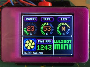
Interface Layout:The screen displays key information including current temperature of the case (both a bar and numeric). The fan icon will show when the fan is on / off (based on animation of the icon, as well as a number in RPM’s (currently not shown). That number dynamically updates every second. The bottom shows the current LED level – an empty bar is off, then it shows % levels based on the switch being toggled.
Scalability:I went with a different approach for this project. I have enough projects under my belt for some lessons learned. A common theme I find is that I want to change things up days or weeks following the completion of any given project. The issue is that when you solder components directly, you run into a mess trying to shuffle or add things. So, I went with a more modular approach:
- Used headers for the Nano. This allows me to swap the unit in/out. I’ve been doing this for the last few projects. It also makes it easy to pull the micro controller out for other projects.
- Headers for all Arduino pins to support future expansion. This has already proven itself in this project as I’ve made numerous pin swaps while working out issues around interrupts etc.
- Sensors / motor control – Use a combination of JST or Molex connectors. This applies to the temperature, fan, and piezo connectors.
- In the future, I may “IoT”-enable this device, so having this flexibility is important.
- Power Supply (up to 3A)
- Silicone Wire (20-24 g)
- DC 12V Fan 4 pin
The Case STL files will be uploaded shortly: Dupont Connector (general search)
Source Code:Although this was built to run on an Arduino Nano, it can easily be adapted to most other duino’s. However, there were few digital pins left after connecting the TFT, so I would stay with a Mini or higher. You will need the following libraries:
- Adafruit_GFX – graphics libraries. Note I slightly modified mine to add a few colours (i.e. Orange). You will get compile errors, but it is easily fixed by adding the necessary colours.
- Adafruit_ST7735 – driver for the TFT.
- SPI – hardware interface to the TFT
- SD – if you are using the SD card on the TFT to render graphics
Arduino Sketch – LulzBot Mini Fan Controller – PlastiBots
Build Pictures:


Comments