

This is a continuation from my first iteration of WIoT weather station. What is WIoT-2? I use it as a cloud-connected (IoT) info center of sorts mounted near our front door. It is a culmination of information my wife or I often look for either on our way out of the house, or when we come home. It displays current/forecast weather from DarkSky.net/WeatherUnderground, weather data from outside the house (from this), date, time, our local waste collection schedule, currency rates, the status of our garage doors (from this), our hot tub temperature (from this), and even allows our kids to check-in when the get home. Read on to find out more about how I built it.
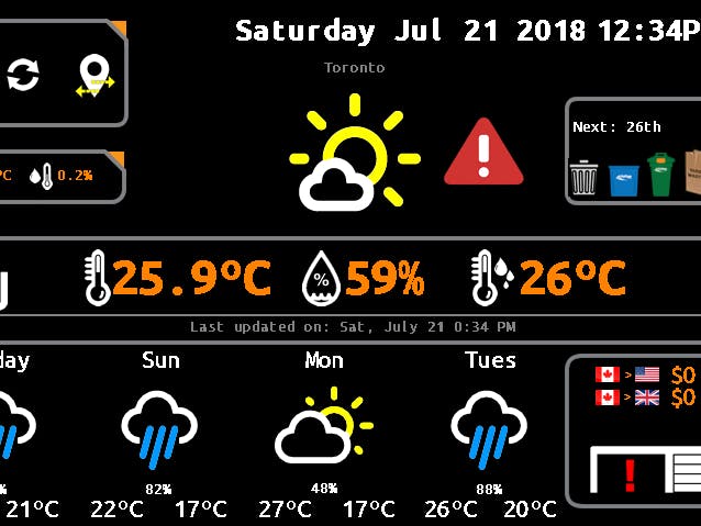
2018 InterfaceWIoT-2 In Action
2017 Version – Mounted to WallWIoT2 Features:- Display current and forecast weather information + alerts. Sources:
- DarkSky.net API or Weather Underground API to pull both current and forecast data in JSON format.
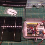
- Display weather data generated outside the house via another ESP unit. It polls temp, humidity and battery info (it’s solar powered) – Integrated with Blynk
- Allows change of weather to different locations (because why not?!)
- Displays temperature and humidity from inside the house. Watch out Nest! 😉
- Poll and display data from our hot tub (integrated with Blynk)
- Open/Close my garage doors, poll/display the status of our garage doors (open/closed) (integrated with Blynk)
- Allow our kids to interact with the unit – sends notifications via Blynk
- Polls waste collection calendar information to show us which waste items are being collected on a weekly basis.
- Show the current date and time – uses Blynk RTC widget
- Shows up-to-date currency conversions CAD>USD, CAD>GBP.
- Master control center for net-connected power outlets in my house (coming soon with SONOFF integration)
I came across the Nextion display over a year or so ago during their Indiegogo campaign. At the time I passed it by as there was not enough information, and frankly I didn’t understand the approach. In hindsight I regret that decision. Itead hit the nail on the head with this display as far as I am concerned. It connects to your MCU (Arduino / ESP8266/32 etc) using a standard 4-wire serial connection as is easy-peasy to program/control. It uses simple serial commands to communicate between the MCU and the display – which is perfect for my needs (and I think most makers like myself). It uses their custom HMI editor (below) which allows you to layout all graphic elements/buttons on the TFT. You can also setup multiple page views to make a very robust visual interface. Refresh and image load rates are fast as well. The concept of using their HMI and how you put graphics and text elements is a lot like object oriented programming, so it was easy to pick up. For those of you using RA8875/1305s and others, you don’t know what you are missing. After spending countless hours coding a prior project using the RA8875 controller, the Nextion is a walk in the park and makes graphical layout and interaction much easier than any other I have dealt with. Anyway, enough on this. I’ve done a more fulsome write-up as to why I like this display so much. There are many other advanced features of the Nextion that I won’t get into here as this is not the purpose of this post.
Pin-Outs & Connections:One of the best things about this project is how easy it is to put together. The connection to the screen uses standard serial (PWR, GND, RX, TX). Then connections to my sensors (PIR 3 wires), Temp/Humidity Sensor (3 wires). Easy peasy!
I’m using the NodeMCU ESP8266, so your connections may be different. This project takes advantage of both Serial ports. Serial is used for comms between the PC and NodeMCU, Serial1 is used for comms between the MCU and Nextion. Well, not exactly. The Node’s Serial RX line is shared on both sides. More on that in a bit. The connections are Node RX to Nextion TX, and Node D4 to Nextion RX. The sketch uses hardware serial using Serial1 (TXD1) to transmit to the Nextion, while return data comes over Serial RX. It sounds more complicated than it is… In the sketch, both Serial and Serial1 have been created. The only trick is that you cant have the Nextion powered when uploading sketches to the Node. I solved this by inserting a latching switch on the Nextion 5V power supply.
Important: Don’t fall into this trap! If you are powering your MCU and Nextion by different pwr sources their GND connections must be common (connected)! Also ensure your power supply has sufficient current to power the Nextion, your MCU and sensors. My go-to is a 5V 3A power supply which always does the trick for me. Also, don’t underestimate the MCU demands on current when it’s using WiFi. The Node jumps to ~500mA when getting data. Here are the connections between the MCU and Nextion: NodeMCU RX >> Nextion TX. NodMCU D4 (TX1) goes to Nextion RX.
Hardware:- NodeMCU ESP8266 V1.0 – MCU (should work with other Wifi-enabled MCUs with minor code modifications). Memory capacity is key – hence why I chose an ESP.
- Nextion TFT LCD 5” (Other sizes: 2.4“, 3.2“, 4.3“, 5.0“, 7.0” ) Click here to find out why I like these displays so much.
- Tiny PIR sensor.
- You will have to build a case to house the MCU and power supply components. In my case, it is on the other side of the wall.
- Switching power supply – provides 5V to NodeMCU and Nextion
- Also works with an ESP32 with minor code modifications.
Nextion Library – Note there is an official Nextion library as well, but this one was sufficient for my needs given it allowed for me to send and receive information from the Nextion. Be sure to read the notes and links (link, link) provided as they give great samples. Note: You can use software or hardware serial. I used hardware serial in my code. If doing this you have to comment out a line in Nextion.h //#define USE_SOFTWARE_SERIAL //Comment this line for use HardwareSerial
- Time – you will also need Paul Stoffregen’s time library for Blynk:
- Arduino IDE – I used 1.6.13, but others should work fine as well.
- Node MCU firmware – comes as part of the ESP package. Google is your friend if you need help. Just google setting up NodeMCU in Arduino.
- Arduino JSON for parsing the JSON data.
- Nextion forums – (a big shoutout to Patrick and Steve for being so helpful in getting me up and running).
- Arduino Source Code & Nextion HMI file – see bottom of page.
Main display at front door
NodeMCU controller unit on backside of wall
NodeMCU + components + case mounted to the backside of the wall.
Garage door status added. Allows monitoring and control of doors.
Blynk Integration:The project also uses Blynk extensively to allow me to view the status and control the various devices I have throughout my house from my phone and tablets. I also use it to debug the devices to ensure they are still sending data at their defined intervals. You don’t have to use Blynk. In my case it simply extends functionality of WIoT and also serves as an alternate controller. For example, I use Blynk to open/close my garage doors when I have my phone. I can also do it using WIoT2.
Outside data is also logged to Blynk. Temp, Humidity and Battery are tracked. Data also reported to WIoT.The Hot Tub controller monitors the temperature and allows the RGBW NeoPixels to be set. Data also reported to WIoT.The Garage Door Monitor allows for monitoring and controller both garage doors. Data also reported to WIoT.
Outside Data Logging Unit
Hot Tub Temp and LED Controller
Garage Door Controller / Monitor
Challenges:I had my first challenge with the NodeMCU when trying to both display debug messages using the standard Arduino Serial window and trying to communicate with the Nextion. After some digging and help from Steve and Patrick on the Nextion forums, I was able to get both Serial debugging and comms with the Nextion. It uses a simple trick in that the Nextion uses the NodeMCU’s D4 pin (Serial 1 TX) to send comms and Serial RX to receive. For those with a keen eye, you can see that this is a problem when uploading sketches – which is easily solved by either disconnecting the pin, or powering down the Nextion display during sketch uploads.
Tips n Tricks:Changing IDs in the HMI Editor: If you haven’t come across this, you will! For the Nextion HMI Editor, once you dump pictures in there, picture order counts as they are all identified by their ID and that ID shifts if you try to shuffle pictures around. Hopefully you don’t have to, but it may be necessary. Using the code sample below to demonstrate, I discovered that the below approach messed up each time I add or shuffle picture objects in the editor. Instead of using the ID of an object, I have the HMI send a print call when any button click sends content back to the MCU. This way, I can check for more realistic values in the call-backs. i.e. I can send “print b1” when button 1 is pressed. You can use whatever text you want, and you can have separate calls when buttons are pressed or released.
Adding New Images / Image Layer Ordering: As I have modified this project regularly since inception, I have also added new images. The issue is the Editor does not have a robust system for moving images up/down layers to put them in front or behind others. There’s a trick to this however. First off, you can replace existing pictures with new ones. So, if you are doing a refresh of an existing image, use the replace feature as it maintains the image ID and does not mess up the others. This is important if your code refers to pictures by their ID # like this code does (for the weather icons). Now, if you go to add a new picture, it will appear on top of all the others. There are up and down arrows at the top left of the Editor that allow you to move objects to the top or bottom of the object display order. No – you can’t do it layer-by-layer, but hopefully they will fix that at some point. Instead, you can use an approach to move the new picture to the bottom, and move others over top of it (if that is what you are looking for). WIoT2 is complicated as I use a background picture that covers the entire screen, so I have to move the new image I added to the bottom, then select the background image and do the same, then any images I want on top of the new picture I simply selected them all and clicked the up arrow. This would be much better if I did a video, wouldn’t it? 🙂
Nextion Baud Rate: You can view the default baud by referring to the ‘baud’ command in the Nextion Instruction Set. Good news is you can also change it by issuing the bauds command with the baud rate you want to use. Don’t forget to update the baud rate in your sketch for Serial1 (i.e. Serial1.begin(9600);). Default from factory is 9600. I changed mine to 115200.
Using Nextion Editor and an ESP in Debug Mode: I discovered this late in the game, but the Nextion Editor has a feature in Debug view that allows you to simulate in a live environment connected directly to your MCU. Doing this is pretty straight forward. In my situation, I have WIoT2 mounted to a wall, so updating it is a pain. To solve this, I have a 2nd NodeMCU unit. I modify the Arduino code and upload to the MCU. The Serial pointer has to change to use the USB serial connection (in the sample code below). After updating the NodeMCU, connect it to USB and your computer. In the Nextion Editor, open your HMI file in Debug view, select the COM port your MCU is connected to and the correct baud rate and you are in business. Your MCU will feed the HMI real data as if it were directly connected to your display. You can watch the virtual display update. When everything looks good, you can build the HMI file and upload it to the physical screen. The only drawback is if you use sensors and do not have back-ups to add to your spare MCU. For me it did not cause issues, but something to think about.
Want to Build it Yourself-Source Code Arduino Sketch / Nextion HMI:
http://www.plastibots.com/index.php/2017/01/03/wiot-2-weather-station-nextion-tft-with-esp8266/


Comments