



Hardware components | ||||||
 |
| × | 1 | |||
| × | 2 | ||||
 |
| × | 1 | |||
Software apps and online services | ||||||
 |
| |||||
| ||||||
 |
| |||||
Hand tools and fabrication machines | ||||||
 |
| |||||
| ||||||
Many real-world tasks require multiple robots to physically interact with different objects, but conventional robotic systems often have limitations:
- Single-task dependency: Many robots are built for specific tasks and struggle when the environment or task changes.
- Poor coordination: Independent robots can have difficulty sharing information and coordinating actions efficiently.
- Complex multi-object environments: Robots need to identify different objects and decide what action is required based on the current situation.
- Scalability: Building a separate intelligent system for every robot increases cost, complexity, and maintenance.
- Real-world uncertainty: Robots must continuously understand their position, surroundings, and the actions of other robots.
Our project addresses these challenges through a centralized Physical AI system that provides a shared intelligence layer for a swarm of physical robots. The system uses vision-based object detection and ArUco-based localization to coordinate multiple robots and dynamically assign physical tasks, enabling collaborative operation in environments such as warehouses, logistics, object handling, and automated material transport.
Our project is a centralized Physical AI system that controls a swarm of autonomous robots using an Arduino UNO Q as the central brain.
System flow:
- Visual Perception: A camera continuously observes the environment.
- Object Detection: An Edge Impulse-trained AI model identifies objects such as a ball, key, screwdriver, and charger.
- Robot Identification: Unique ArUco markers on each robot allow the system to identify every robot.
- Real-Time Localization: The system calculates each robot’s position and orientation within the workspace.
- Decision Making: The centralized brain combines object detection, robot locations, and the current task to determine what needs to happen next.
- Task Assignment: The appropriate robot or group of robots is assigned a physical task.
- Motion Planning: Robots autonomously move toward the required location while continuously updating their position.
- Physical Interaction: Robots interact with and transport objects to complete the assigned task.
- Continuous Feedback: Camera observations are continuously used to update the swarm’s state and make the next decision.
For example, the swarm can detect a ball, determine which robot should approach it, track its movement, and coordinate the robot’s motion toward a designated goal. This architecture can be expanded to multiple robots performing different or collaborative physical tasks.
Why Arduino UNO Q?The Arduino UNO Q is the core of our system because it provides the computing capability needed to act as the centralized brain of a Physical AI swarm.
- On-device AI: The UNO Q allows AI/ML workloads to run locally, enabling the system to process visual information without depending entirely on cloud computing.
- Real-time decision making: Local processing reduces communication and cloud latency, allowing the swarm to respond quickly to changes in the environment.
- Vision-based perception: The board can process information from the camera and use our Edge Impulse-trained model to identify objects such as balls, keys, screwdrivers, and chargers.
- Centralized swarm control: A single UNO Q can combine object detection, ArUco-based robot localization, and task information to coordinate multiple physical robots.
- Physical AI integration: Its combination of computing and microcontroller capabilities allows the AI decisions to be directly connected to real-world robot motion and physical interaction.
- Scalability: The centralized architecture allows additional robots to be added without requiring a complete AI system to be developed for every individual robot.
This makes the UNO Q suitable as the bridge between AI perception, autonomous decision-making, and coordinated physical action in our multi-robot swarm.
2. Components Used (BOM)Component XQty
Arduino UNO Q (ABX00087) X1
[1031134] Type-C USB 5V 2A Step-Up Boost Converter with USB Charger X1
[R101322] DMEGC INR18650-26E 3.7V 2600mAh Li-Ion Battery X2
[130214] 18650 SMD/SMT High-Quality Single Battery Holder X2
[62858] MINI 3PI car N20 Caster Robot Ball Wheel X4
[1150680] 3.7V to 12V Mini DC-DC Boost Step Up Converter Board Module 5V/ 8V/ 9V 12V Output X2
Numakers PLA+ Filament- Pure White (1.75mm/ 1kg Spool) (Color is optional) X1
N20 DC Motors 100rpm X4
N20 DC Motors Wheels 50mm DIameter X4
Logitech C270 Digital HD Webcam X1
TOOLS:
Pro-Range Soldering Iron Kit with Smart Digital Multi-Meter
Miscellaneous:M2 X 4mm Phillips Pan head SS 304 Screw (Dia. 2mm, Length 4mm) X8
Pro-Range 12 sizes Heat Shrink Tube kit 850pcs X1
Pro-Range 30AWG Extra Soft Tinned Stranded Silicone Wire Kit - 5Colors X 10m(50m)-600V High and Low Temperature Resistant X1
Pidilite Flex Kwik Instant Adhesive Fast Bonding for Flex and PVC Doors (20g) X1
Manufacturing Resources:
Robu Online FDM 3D Printing Service
3. System Architecture & CircuitStep-by-Step Workflow
Summarised Workflow:
Detailed Step-by-Step Workflow
1. Camera Captures the Environment
A camera continuously observes the robot workspace and captures the current state of the environment. The camera provides the visual information required by the centralized Physical AI system, including the locations of objects and robots.
2. Edge Impulse AI Detects Objects
The captured images are processed using an Edge Impulse-trained computer vision model. The model has been trained to recognize different objects relevant to the robot's tasks, such as a ball, key, screwdriver, and charger.
The detected objects provide the system with information about what is present in the environment and where the objects are located.
3. ArUco Markers Identify the Robots
Each robot has a unique ArUco marker placed on top of its body. The camera detects these markers and identifies individual robots within the workspace.
The system uses the marker information to estimate each robot's position and orientation, allowing the central controller to understand where every robot is and which direction it is facing.
4. UNO Q Builds the Current Environment State
The Arduino UNO Q acts as the centralized brain. It combines information from object detection and robot localization.
The system can therefore maintain an understanding of:
- What objects are present
- Where the objects are located
- Which robots are available
- Where each robot is located
- The orientation of each robot
- The current progress of the task
This creates a continuously updated representation of the physical environment.
5. Centralized Physical AI Makes the Decision
Based on the detected objects, robot positions, and the assigned objective, the centralized system determines the next action.
Instead of every robot independently deciding what to do, the centralized brain coordinates the swarm. It can determine which robot is best positioned to perform a particular task and where that robot needs to move.
For collaborative tasks, the system can also determine when multiple robots need to participate.
6. Commands Are Sent to the Robot(s)
Once the decision is made, the UNO Q sends movement or task commands to the appropriate robot or group of robots.
For example:
Detected ball → Select suitable robot → Calculate target position → Send movement command
This allows the centralized intelligence to translate visual understanding into physical actions.
[IMAGE SPACE — UNO Q communicating with multiple robots]
7. Robots Navigate Toward the Target
The selected robot begins moving toward the required location. During movement, the camera continues observing the robot and detecting its ArUco marker.
This provides continuous feedback about the robot's actual position and orientation. The system can therefore update its movement decision rather than relying only on a pre-programmed path.
8. Robot Performs Physical Interaction
After reaching the required location, the robot performs the physical part of the task.
Depending on the objective, this could involve approaching, pushing, carrying, transporting, sorting, or manipulating an object.
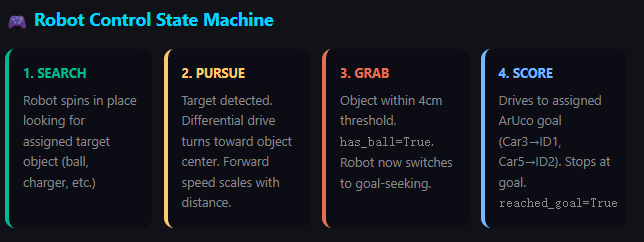
For example, in the current demonstration, a robot can detect and move toward a ball and then transport it toward a designated goal.
9. Continuous Visual Feedback
After the robot performs an action, the camera captures the updated environment again.
The system checks the new state using:
Camera → Object Detection + ArUco Localization → UNO Q → New Decision
This creates a continuous perception–decision–action feedback loop rather than a one-time command.
10. Swarm Coordinates the Next Action
The process continues until the overall objective is completed.
Because the intelligence is centralized, multiple robots can be coordinated to perform sequential or collaborative tasks. One robot can complete one part of a task while another robot performs the next operation, or several robots can work together when a task requires multiple physical agents.
The architecture is designed so that additional robots can be introduced without needing a completely independent AI system for every robot.
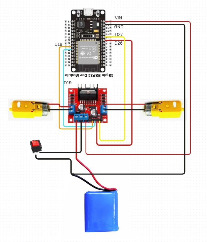
Block Diagram & Circuit Schematic
During validation, the model achieved an F1 score of 86.2%, with approximately 82% precisionand 91% recall. The reported on-device inference time is approximately 9 ms, with about 114.7 KB peak RAM usage and 81.2 KB flash usage.
The separate model-testing results achieved approximately 57.89% overall accuracy, with 81% precision, 71% recall, and 76% F1 score. This testing result demonstrates that the model still has room for improvement when exposed to unseen conditions, which is important for future iterations of the Physical AI system.
The model uses a FOMO (Faster Objects, More Objects) MobileNetV2 0.35 object-detection network trained in Edge Impulse to identify six objects: Arduino, ball, bike key, charger, screwdriver, and screw driver.
The model processes camera frames at 96 × 96 pixels and provides both the detected object class and its approximate location in the image. The Arduino UNO Q combines this visual information with ArUco-based robot localizationto decide which robot should move toward an object and what action should be performed.
The model can degrade when objects are partially occluded, very small, too far from the camera, poorly illuminated, or viewed from angles and backgrounds that are significantly different from the training data. Similar-looking objects, such as the two screwdriver classes, can also cause misclassification.
Performance may also decrease in cluttered environments where multiple objects overlap. These limitations can be reduced by expanding the dataset with more viewpoints, lighting conditions, distances, backgrounds, and real-world operating scenarios.
GitHub Repository
https://github.com/vikas-meu/physical_ai_challenge_robu.git
Demo Video Link


Comments