


In our house we operate a WTW already for 14 years now. It is a non-connected (not on-line) ventilation machine that takes fresh air from outside the house which after filtering is flown into the house. The fresh ambient air is preheated with air that is taken from most rooms in the house. The energy for reheating is taken from the outflow of “dirty“ air by means of heat exchangers. This setup minimizes ventilation-related energy loss by reusing heat from outgoing air.
WTW is a Dutch abbreviation for “Warmte Terug Winning“ or in English: “Heat Back Winning“. (lit.), a balanced ventilation system with heat recovery.
This project upgrades an existing Brink Renovent Excellent 400 WTW without losing manual switch control and adds LED indicators for life status feedback.
The existing WTW is manually controlled with a 3-state manual selector switch on the ground floor, whereas the WTW itself is located in the attic.
The 3 states of the switch are related to the (user-set) airflow volumes, as follows:
· S1: Low airflow (50m³/hr, used when nobody is home for longer periods)
· S2: Normal airflow (150m³/hr, used as the normal day & night flow)
· S3: High airflow (300m³/hr, used only when needed)
The red LED, when lit, indicates that the WTW filters (inlet and outlet filter), should be cleaned. Note that this switch controls the airflow in the whole house, not only the bathroom. (not so smart, but there are no valves for individual control of the various rooms).
In the bathroom there is air suction to the WTW and also an Electrically Heated Towel Rack, controlled with a time-controlled thermostat and a Zigbee Smart Plug. For energy-saving purposes, we reduced the time for heating (1200W) the Towel Rack. This, however, has as consequence that humidity stays longer in the bathroom after taking a shower or bath (at normal airflow). Mirrors and windows may get fogged and the risk of mold growth increases. To solve this it is possible to put the airflow of the WTW in the highest position with the manual switch. However, in the highest ventilation position, the WTW uses significantly more electrical energy than in the normal state. When one forgets to turn the manual switch back to its normal state S2, a lot of energy can be wasted unnecessarily.
This situation was the reason for creating this project: the design and build of a system that takes over control from the manual switch and controls the WTW in a smart automatic way.
The system monitors bathroom humidity with a Zigbee Temperature and Humidity sensor and temporarily overrides the Brink WTW’s standard manual ventilation control using a 1-channel Zigbee smart Switch. Humidity readings trigger Smart Life scenes that control the Zigbee switch. These scenes can be made and modified in the Smart Life/Tuya APP.
When someone takes a shower and the humidity level crosses 70% (programmed pre-set value), a Zigbee Smart Switch module is activated to switch the WTW into S3 (high airflow). Once the humidity in the bathroom has dropped below a user-defined level, the relay in the smart switch returns to its NC (Normally Closed) position and restores S2 (normal speed). The original 3-speed wall switch remains in place and remains usable. The lowest airflow (S1) remains manually controlled as this is only necessary when we go on holiday. All wiring and electronics are packed in a small 3D-printed box (module), that is placed in line with the existing cabling with a male RJ12 plug from the manual 3-state selector switch and the (female ) RJ12 plug on the WTW. By doing so the original situation can easily be restored. The module is placed on top of the WTW-unit.
To enhance its functionality, the module includes:
· A mirrored filter warning LED (red)
· Ventilation speed indicators (green LED for S2, blue LED for S3)
This setup provides meaningful feedback on the WTW, where the manual switch is out of view. It is also possible to modify the Smart Life scene to include functionality, based on data from a smart CO₂-sensor, to make the ventilation logic even smarter (not implemented here).
1.1 Existing Solutions on the market
There are quite a few solutions available on the market. Most commercial systems focus on large-scale building automation or integrated HVAC platforms, often with proprietary controllers and cloud dashboards.
What makes this Project unique?
This project is bridging the gap between maker-grade flexibility and consumer-grade simplicity. Most solutions either go full industrial or full smart-home; this one is a targeted on retrofitting a specific but common use case:
- No coding required — just Smart Life scenes
- Preserves manual switch control
- Adds visual feedback (LEDs)
- Expandable with CO₂ logic
- Open-source and reproducible
- Custom 3D-printed enclosure
Even though the Brink Renovent Excellent 400 is most common in the Netherlands and parts of Western Europe, the control method in this project can be applied to other ventilation units with similar multi-speed input logic. This project is designed to inspire replicable upgrades for many similar brands of balanced mechanical ventilation.
2. Things used in this project
The following things have been used for this project:
Software apps and online services
- Smart Life / Tuya
- Autodesk Fusion 360
- CURA
- Easy EDA
The design of the Smart WTW control system is based on the following requirements:
- It should be placed in-line with the existing connection from the 3 State manual selector switch to the existing WTW unit.
- It should be based on the use of a Zigbee smart switch module.
- It should me managed with the Smart Life APP.
The system diagram is shown below:
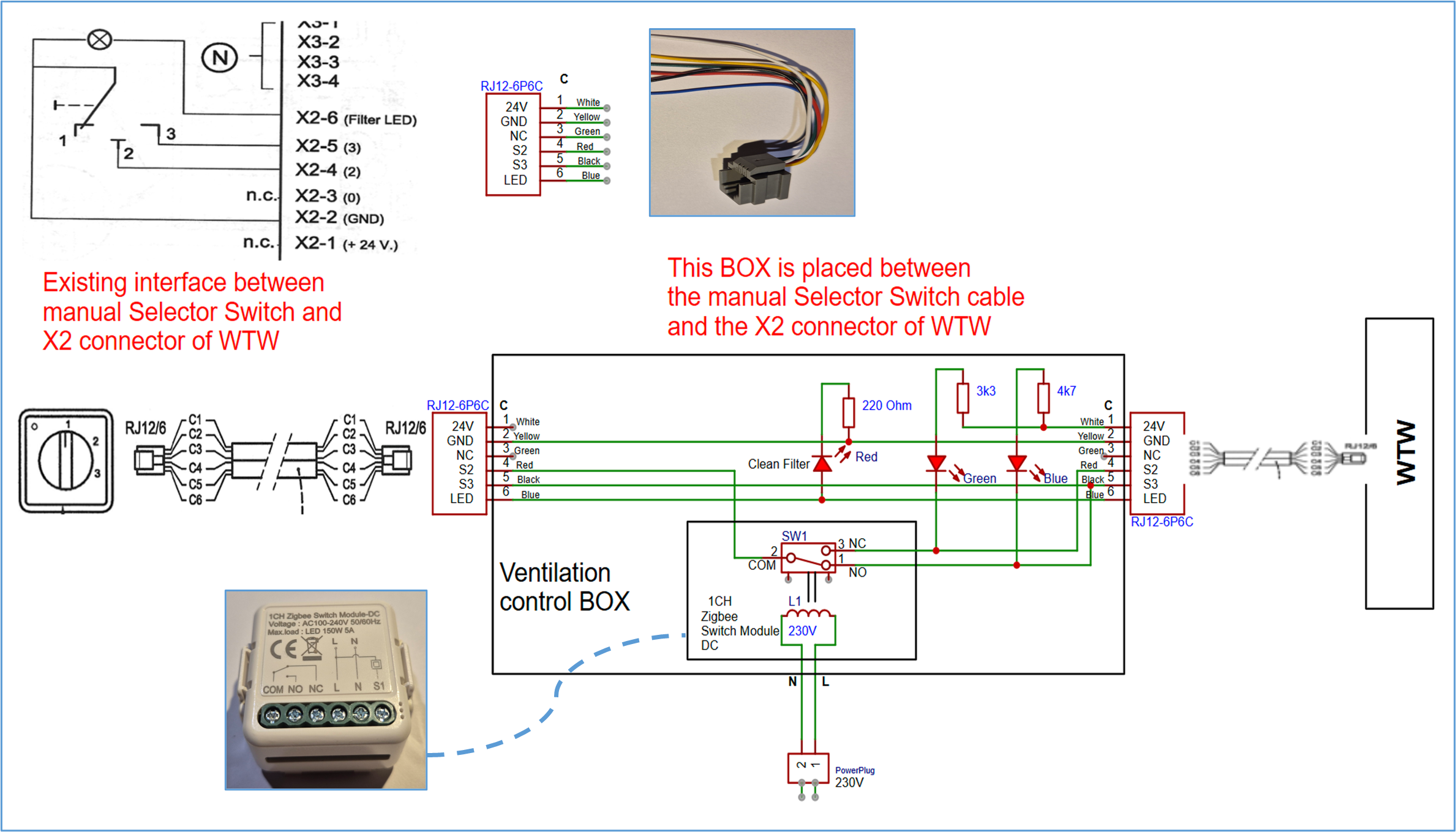
Wiring Diagram
The full wiring diagram showing the manual selector switch interface, LED logic, Zigbee relay integration, and RJ12 connectivity is as follows:
How It Works
- Defaultmode: Manual wall switch sets ventilation to S2.
- Humidity > 70%: Smart Life turns Zigbee relay to NO, breaking S2 and engaging S3.
- Humidity < 60%: Relay turns NC, system returns to S2.
- Speed & Filter LEDs: 3 LEDs show active fan mode and filter maintenance state.
3.1 Building the Hardware
Step-by-Step Guide
- Prepare Components
- Gather all items listed in the Things Used section.
- Wire all components
- Wire components on the breadboard-style PCB as shown in the schematic.
- Use a 6 wire flat cable to mount an RJ12 (6P6C) connector.
- 24V power for the Green and Blue LED is taken from the WTW X2 connector.
- Attach 230V L and N to relay using a safe mains cord. Ensure correct polarity (L and N) for AC mains. Some Zigbee relay modules may malfunction if these are reversed.
- Install Indicator LEDs
- Red LED: Connect anode to filter LED signal from X2 connector and cathode (-) via a resistor to GND
- Green LED (S2): Anode via 3.3 kΩ to +24 V, cathode to S2 line.
- Blue LED (S3): Anode via 3.3 kΩ to +24 V, cathode to S3 line.
- Assemble Enclosure
- 3D Print the enclosure parts using the provided.stl file. I used PLA in silver color, with 15 % infill at 2200 C.
- Secure all components inside the 3D-printed housing.
- Ensure proper insulation for 230 V lines.
- Test and check all wiring
- Check all wiring (use a multimeter)
- After testing, connect the Box in-line between the all switch and the Brink WTW.
- Pair Devices
- Add the Zigbee module and humidity sensor to the Smart Life app.
- Test scene behavior and adjust thresholds as needed.
- Monitor System
- Verify the LED states and humidity-triggered ventilation.
RJ12 Pinout and Color Code Details
LED Resistor selection
To ensure proper brightness and longevity of the LEDs, resistors were calculated based on the following:
- Red LED (Filter): 5V from WTW, → Resistor = 220Ω
- Green LED (S2): 24 V from WTW → Resistor = 3.3 kΩ
- Blue LED (S3): 24V from WTW → Resistor = 4.7 kΩ
The reason for selecting different resistor values for the Green and Blue LED’s is because of their different forward voltage characteristics.
3.2 The result of the assembly work
Below is the completed assembly of all the components (except the power cable) on the prototype breadboard:
Once everything has been mounted in the 3D printed enclosure, the result looks as follows:
Note that the power plug has been marked with L and N, to avoid connecting it wrongly to the 230V wall outlet. Also visible on the inner side of the box, is the strain relief for the power cable. The 3D printed enclosure allows easy insertion of the RJ12 female entry connector into the bottom part of the box. The outgoing flat cable with male RJ12 connector is easily clamped between the bottom part and the top part. The reset button of the Zigbee module is accessible via a printed hole in the frontside of the box.
Finally the top part of the box is snapped on the bottom part. The top part can be easily removed with a flat screwdriver in the slots made in the top part.
After mounting the top cover on the Box the result is as shown below:
3.3 Smart Life Automation
In order to work with Smart Life and use its automation capabilities, you need to install the Smart Life APP on your mobile device and create an account. To do this go to : https://smartapp.tuya.com/SmartLife and scan the QR code or Search for the "Smart Life" app on the Play Store or Apple Store. Open the app and follow the instructions for setting up a new account.
You will also need to install a Zigbee HUB (e.g. https://m.media-amazon.com/images/I/51s9RroskML._SL1001_.jpg for the “MOES Tuya Smart ZigBee Wired Gateway Multi-Mode with BLE-Wifi 2.4G Mesh Hub,Voice Control via Alexa Google Home”)
For setting up this Hub follow the instructions in its enclosed manual.
Once you have done that you can proceed with adding the Humidity sensor and the 1 Channel Smart Switch module.
To set up the automation go to the bottom of the home screen in Smart Life and select “Scene”:
Then click “Create Scene”
You then get the following screen, Select “When device status changes”
Then the following screen appears:
From the list, that is shown, select the already added Temperature & Humidity sensor:
Select the “Current Humidity”
Make the settings as indicated with the red arrows and finally click “confirm” <Bevestigen>
You then return to the “Create Scene” screen.
Click the ”+” in the “Then”-box, to add an action.:
Note that “Precondition is set to “Full day”, but you can choose a different time slot, e.g. day time, when your solar panels are (over) producing electric energy.
As action, select Device:
In “Device”, select “single device”. Then from the list of devices, select your 1CH smart switch under whatever name you have given it before:
You then get the following screen, where you make the settings as indicated with the red arrows:
Don’t forget to confirm <Bevestigen>. You then return to the “Create Scene” screen. Check if everything looks OK. In the “Display Area” you can select the room to which you want to allocate this smart scene.
When returning, to this screen, make sure you “Save” your Scene: <Opslaan>
Give your scene a name and confirm:
Now you have made the first part (Scene A) of the automation, which is the part that puts your Smart Switch in the “ON” mode, whereby the built-in relay will switch to S3 (high ventilation volume), if the humidity in the Bathroom get higher than 70%.
Scene Setup
- Scene A:
- IF Humidity > 70%
- → THEN Turn ON Zigbee relay (forces S3)
- Scene B:
- IF Humidity < 60%
- → THEN Turn OFF Zigbee relay (returns to S2)
You can adjust all values for humidity threshold in the Smart Life APP. It is also possible to enhance the logic later, e.g., based on CO2 levels in a room.
You should now be able to make Scene B yourself applying the same procedure as for Scene A. The result should look like this:
This project demonstrates how you can enhance an existing ventilation system with smart automation while retaining manual control. By integrating Zigbee devices and Smart Life scenes, you can achieve energy-efficient humidity control and improve air quality.
This project has been tailored for a particular type of WTW, however it can be easily adapted for different types of ventilation systems or even other equipment that requires a simple selector switch to be automated to make it “Smart”
Feel free to adapt the design for other ventilation systems or expand functionality with additional sensors.
Writing this tutorial was a pleasant thing to do, hope it is useful to you
Have fun reading and/or making your own Smart Ventilation System!


Comments