

Hardware components | ||||||
 |
| × | 1 | |||
 |
| × | 4 | |||
 |
| × | 4 | |||
 |
| × | 4 | |||
| × | 1 | ||||
_ztBMuBhMHo.jpg?auto=compress%2Cformat&w=48&h=48&fit=fill&bg=ffffff) |
| × | 1 | |||
Software apps and online services | ||||||
| ||||||
Hand tools and fabrication machines | ||||||
 |
| |||||
| ||||||
This project is about controlling multiple relays or other actuators from a single Arduino output pin.
This solution can be used for typical situations where the amount of available Arduino output pins is insufficient and more actuators such as relays need to be controlled in parallel from a single output pin.
The principle of operation is based on using a LED strip of a number of NeoPixels (SMD5050 LEDs with WS2812B controller chips). Every pixel is put together with an LDR (Light Dependent Resistor), thus creating a DIY optocouplers (as many as you want, only limited by the LED strip length, e.g. 300 pixels, and available 5V power supply). In this way a serial to parallel conversion is created (from 1 to many)
Every individual LED is addressed from one and the same Arduino output pin. Each LDR (in series with a 27kOhm resistor), is connected to a 5V relay. In this way many NeoPixel/LDR combinations can be controlled from 1 Arduino output PIN using the Adafruit NeoPixel library. Instead of relays also other actuator devices could be connected, using the LDRs as an input to whatever circuit.
For this project, which is part of a bigger plan, an ESP32 (NodeMCU) is used; however a normal Arduino Uno (or almost any other model) will do the job.
Step 1: Making the NeoPixel OptocouplersThe DIY optocoupler is made with the following materials:
- a piece of LED strip consisting of 10 WS2812 LEDs (cut from a longer strip) only 4 are actually used in the project
- a piece of dark grey foam
- a strip of breadboard
- black duck tape
Note: the separation of the dots equals the separations of the LEDs.
It is important to separate the light of each individual LED from the LDRs of the others to avoid "light cross talk." It turned out that in practice this is almost impossible and therefore the amount of light emitted by each LED in the "on" state has been set to low levels in the software.
The LED strip used is 10 LEDs long but only 4 pixels are used in combination with 4 LDRs in this project (to keep it simple)
Step 2: The Electronic SetupIn the breadboard set up, I used an ESP32s (NodeMCU), however any Arduino can do the job.
The circuit diagram (made with Fritzing) is as follows:
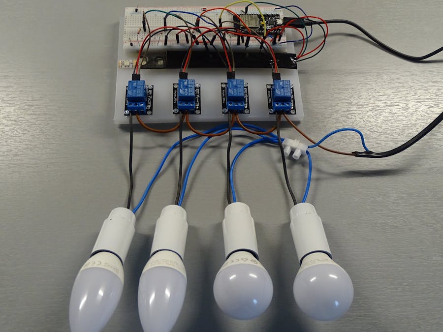
In practice this looks as follows:
As you can see only 1 output pin is used to control 4 relays in parallel. This number can go up as high as 300! (as many LEDs as available in a 5 m long strip).
The ESP32 device works at 3.3 Volt levels (an on-board 3.3V voltage regulator), while the LED strip with 5050 leds runs on 5 V. The ESP32 is fed with 5 V power (via the USB port from a 5V adaptor or 5V powerbank). The NeoPixel LEDs get the 5V supply directly from the 5 volt pin of the ESP32 and the relays used, are also 5V types.
In this example 4 optocoupler circuits are used controlling 4 relays connected to one 230V lamp each.
The output pin used is GPIO PIN 21 and the relays are controlled via pixel numbers 1, 2, 3, 4.
Step 3: Making the SoftwareThe loop function in the Arduino Sketch is simple and consists of a number of "for"-loops to show different patterns of switching the lamps by controlling each of the relays.
To control a particular relay the following function is called from within the loop code:
void ControlRelais (int RelaisNo, bool RelaisState)  {
   strip.setPixelColor(RelaisNo, RelaisState*15, RelaisState*15, RelaisState*15);      // turn on/off the LED that belongs to RelaisNo
   strip.show();
   Serial.print(" RelaisNo "); Serial.print(RelaisNo); Serial.print(" = "); Serial.println(RelaisState);
   }
In fact all this function does is either switch on a particular LED or switch off.
A LED address corresponds with the respective relay number. The LEDs are lit at a low light level, just enough to trigger the relay via the LDR, and thus avoiding light pollution (also referred to above as "light cross talk".
The result of all the effort and the particular sketch, is shown in the following movie:


_3u05Tpwasz.png?auto=compress%2Cformat&w=40&h=40&fit=fillmax&bg=fff&dpr=2)
Comments