

Hardware components | ||||||
| × | 1 | ||||
| × | 1 | ||||
| × | 1 | ||||
_ztBMuBhMHo.jpg?auto=compress%2Cformat&w=48&h=48&fit=fill&bg=ffffff) |
| × | 1 | |||
| × | 6 | ||||
| × | 1 | ||||
| × | 1 | ||||
Software apps and online services | ||||||
 |
| |||||
Water reservoir tanks are used for many purposes, e.g. in a Caravan or Camper or in Plant Watering installations, etc. Often there is no direct visibility of the available amount of water in the tank. There are various ways to measure water levels in reservoir tanks, you can buy them at significant prices or make one yourself!
As opposed to: Bring your Own Device -> MAKE YOUR OWN DEVICE!
I decided to make a Water Level Sensor and also a Water Level Indicator with 5 levels.
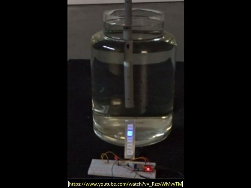
Here you can watch the result:
Step 1: Making the Water Level SensorThe DIY Sensor is made with simple materials:
- 6 pieces of electricity wire (1, 5 mm copper with black PVC cladding) stripped approx 1 cm at both ends
- a piece of electricity pipe 3/4 inch with a length that matches the depth of your reservoir
- 1 PVC 3/4 inch pipe extension
- 6 * 680KOhm resistors
- a 1 nF capacitor (for noise suppression)
- a cheap audio cable
- a piece of double sided prototype PCB board
Note that drilling some 5mm holes in the pipe is essential.
The principle of operation of the Water Level Sensor is based on the conductive properties of the water. The higher the salinity, the higher the conductivity, equivalent to lower resistance. The average conductivity value of the tap water supplied in my area is approx 35 mS/m. The more copper probes are in the water, the lower the resistance of the ladder network is. This lower resistance value results in a higher input voltage to the 12 bit ADC at the GPIO pin of the ESP32. With this set up it is possible to measure 5 different waterlevels.
The electronic scheme of the sensor is as follows:
All parts are assembled and soldered together:
The assembly is put in the 3/4 inch pipe extension and filled with transparant silicone to make it waterproof.
The cable used for connecting the sensor to the Arduino is a cheap audio cable from the local ACTION store
The fully assembled Water Level Sensor seen below:
The components used for the indicator are:
- a piece of dark grey cutting board (from ACTION) with holes drilled as can be seen in the next picture and using a file to make the holes square
- a piece of LED strip consisting of 5 WS2812 LEDs (cut from a longer strip)
- photo paper with the 5 levels printed (1%, 25%, 50%, 75%, 100%)
- a piece of transparant foil for protection of the print
- Aluminium foil as a cover (not very easy to handle, but this is what I used)
The final result of the assembly work can be seen below:
The breadboard set up is shown in the following picture:
In this set up I used an ESP 32s (Node MCU). The reason for this choice is the fact that I plan to expand this set up with functionality for making a complete plant watering system with on-line monitoring and warnings. (the ESP 32 has WiFi and Bluetooth on board).
The circuit diagram (made with Fritzing) is as follows:
The ESP 32 is powered with 5 V from the USB port and has a 3, 3V regulator on board. One output GPIO pin is directly connected to the Water Level Sensor and sends a 3, 3 V signal to the sensor with a duration of just 200 milliseconds. This is to avoid electrolysis effects in the water and consequently corroding of the copper ends.
The output from the Sensor is connected to two 1 M Ohm resistors that form a "virtual Wheatstone bridge" with the Sensor and a comparator array in the software.
I used this set up, because the behaviour of ladder network in the water as a function of the waterlevel is non-linear (see below diagram):
Theoretically, when the sensor is not in the water the measured value at the sensor pin is approx 1,0855 V which would be equivalent to 1347 bits. The deviation with the graph can be explained with tolerances of the resistors, the resistance in the sensor wire, deviations in the 3,3 Volt supply of the ESP 32 and some non-linearities in the 12 Bits ADC of the ESP32 as well as some noise in the circuit.
The 5V power for the 5 LEDs used in the Level Indicator is derived directly from the 5V pin (connected to the 5V input from the USB port);
During my experiments, it turned out that using a 5V telephone charger gave different results than the 5V USB port of the PC or from a 5V power bank. The power bank, although providing stable results, switches off (sleeping mode), however, after a short while, because of the low current drawn by the system.
Step 3: Making the SoftwareThe loop function in the Arduino Sketch is simple and consists only of the calling 2 functions:
void loop(){
 MEASUREWATERLEVEL ();
 INDICATEWATERLEVEL ();
 delay(1000);                            // Check for new value every 1 sec;
The 1 second measurements are just for experimentation and demonstration purposes. In practical applications this will be far less frequent (depending on how quickly the water in the reservoir is used)
The plot monitor of the ARDUINO IDE as well as the serial monitor have been very useful during experiments. A view of the plot monitor graph is given below.
The Graph shows the (1 second) measurements of the sensor going down and up into the water (green line); the red line represents the reference values as set in the LEVELarray []. These values have been determined by experimentation and clearly show the non-linear behaviour of the sensor.
//                      0    1    2    3    4    5
int LEVELarray [6] = {1125,1245,1450,1720,2080,2630} ;
The "0" level is applicable when there is no water in the reservoir, the "5" level is applicable when the reservoir is full.
The non-linear behaviour of the sensor could be corrected by making a ladder network with non-uniform distributed resistor values.
I concluded that it is much easier to deal with this in the software.
Also the natural jitter that exists on the measured sensor values can easily be eliminated in the software by a allowing a tolerance on the measured values of e.g. 4%, (also note the 220nF capacitor in parallel with the two 1 M Ohm resistors)
for (int i = 0; i < 6 ; i++)
   {
if ((WaterLevelValue > (LEVELarray[i] * 0.96)) && (WaterLevelValue < (LEVELarray[i] * 1.04)))
// allow a margin of 4% on the measured values to eliminate jitter and noise
     {
     level = i;
     }
Finally the level as determined above, is used to display the water level on the Level Indicator with a color, which is very easy thanks to the <Adafruit_NeoPixel.h> library:
redVal = color_scheme[level*3];
greenVal = color_scheme[level*3 + 1];
blueVal = color_scheme[level*3 + 2];
strip.setPixelColor(level-1, strip.Color(redVal, greenVal, blueVal) );
strip.show();
For downloading the sketch through the USB port onto the ESP 32, it is required to hold down the Boot button.
NOTES:
When using a regular ARDUINO (e.g. UNO) instead of the ESP 32, a number of changes need to be made in the code such as:
- the pin allocations
- The values in the LEVELarray, taking into account that the UNO has a 10 bit ADC (on pin A0); first best guess is dividing the values by 4
- The 5V trigger pulse to the Sensor (instead of 3, 3V) should not have an impact
You may discover an extra 680 kOhm resistor in the practical set up on the breadboard compared to the Fritzing diagram. This is because initially, I wanted to have the "0" sensor wire be disconnected from the ladder network (for experimentation reasons), so I used also a 3 wire sensor cable, whereas in the final design only 2 are needed.
I am interested to hear if someone is actually going to reproduce this project.
Developed and produced by Pierre Pennings (December 2018).


Comments