

Hardware components | ||||||
_ztBMuBhMHo.jpg?auto=compress%2Cformat&w=48&h=48&fit=fill&bg=ffffff) |
| × | 1 | |||
| × | 1 | ||||
| × | 1 | ||||
| × | 2 | ||||
| × | 1 | ||||
Hand tools and fabrication machines | ||||||
 |
| |||||
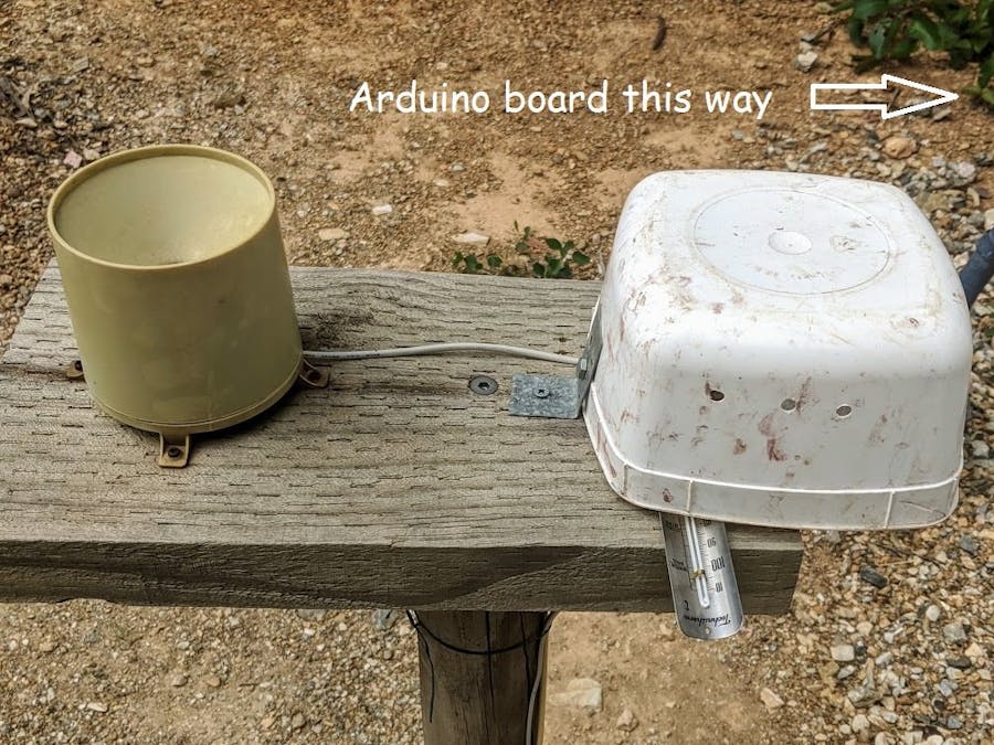
I mainly wanted to collect rainfall data from an inexpensive rain gauge that works well, but the the output unit the gauge was connected to was very limited - just a rolling record of the rainfall for the previous 7 days. I included some temperature sensors so I could call it a weather station and now I can tell when and how much rain our garden has received, particularly if I've been away for a few weeks. The project is based on an Arduino Uno with a data logging shield and two thermistor sensors for temperature.
The novel aspect in the sketch is combining the logging of temperature data at a specified interval with rainfall events that can occur at any time.
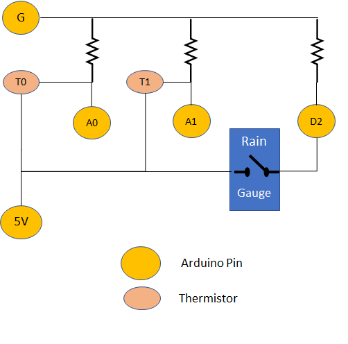
The schematic for the connections is simple. I used the perfboard on the data logging shield to house one of the temperature sensors and a terminal block for the wired connections to the rain gauge and other sensor. My next challenge is to make it wireless!
From the readme file accompanying the sketch:
Description
A data logger shield with RTC was used to log results of weather sensors to an SD card.
Analog pins 0 and 1 were used to monitor two thermistors and digital pin 2 was used to monitor the state of a magnetic switch in a tipping bucket rain gauge.
The loop function accommodates a set interval for reading the thermistors as well as detecting whenever the rain bucket tips.
Instead of using the delay function to dictate when data is logged, logging is triggered during the loop cycle in which time elapsed exceeds the LOG_INTERVAL. This is to ensure the Loop cycle is frequent enough to detect the transient bucket tip events.
The StateChangeDetection example sketch in the Arduino Editor was adapted to register a bucket tip. Conversion of bucket tip events to mm of rain is can be done in a spreadsheet, or in code:
rainfall (mm) = rain gauge collection area (cm2) x volume of water (cm3 or mL) needed to tip the bucket x 10.
In my gauge, 100 mL of water slowly poured into the collection area resulted in 16 tips -> about 16.5 mL per tip. The collection area is 63.6 cm2 so a tip is equivalent to 0.98 mm rain
Code for thermistors was adapted from Circuit Basics:
(http://www.circuitbasics.com/arduino-thermistor-temperature-sensor-tutorial/)
This computation, using values for parameters a, b and c provided in this tutorial seems to produce something close to what my glass thermometer says, however the two thermistors next to each other differ by about 0.5 C, so some calibration is needed.
A data logger shield with RTC was used to log results to an SD card. Code for data logging and SD file management was adapted from an Adafruit page:
https://learn.adafruit.com/adafruit-data-logger-shield/using-the-real-time-clock-3
Installation
A wired tipping bucket rain gauge was used in place of a button switch in the layout for the StateChangeDirection example sketch.
NTC thermistor modules, incorporating a 10k resistor were used for temperature.
The datalogging shield was piggybacked to an Arduino Uno board and the perfboard area used:
- to connect one of the temperature sensors,
- incorporate the rain gauge voltage divider resistor,
- to route connections between the pins (voltage, ground, analog and digital) and the remaining (remote) temperature sensor and rain gauge, via a terminal block.
The assembly was powered by a 10 V power supply (from my collection of power supplies from discarded devices).


Comments