

Hardware components | ||||||
 |
| × | 1 | |||
 |
| × | 2 | |||
 |
| × | 1 | |||
 |
| × | 1 | |||
 |
| × | 1 | |||
 |
| × | 1 | |||
 |
| × | 1 | |||
| × | 1 | ||||
 |
| × | 1 | |||
| × | 5 | ||||
| × | 1 | ||||
| × | 1 | ||||
| × | 1 | ||||
_ztBMuBhMHo.jpg?auto=compress%2Cformat&w=48&h=48&fit=fill&bg=ffffff) |
| × | 1 | |||
Software apps and online services | ||||||
 |
| |||||
Hand tools and fabrication machines | ||||||
 |
| |||||
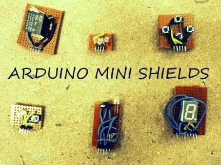
Presented here are the Arduino Mini shields. These shields are very easy and fun to make. Arduino shields are very useful for the Arduino to help you out in some very common projects like IR communication, relay controlling, etc. These shields are also portable. You can also make your own custom Mini Arduino shields.
In this project, I experienced that each shield is like a mini electronic project. And I think it would be nice project for beginners with Arduino. First of all, I made the relay shield. I started making it a week ago and one by one I completed all six of them. Now, I have presented here six Arduino shields:
- IR Communication Shield
- Debouncing a Button Shield
- Light Sensing Shield
- D-Pad Shield
- Seven Segment Display Shield
- Relay Shield
I have also provided codes for testing your mini shields to show that all shields are fully functional. You can also make a custom shield of mini shields.
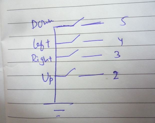
D-Pad Mini ShieldThe D-Pad mini shield is the directional input for Arduino. By applying the code and making the circuit, you can get the display of the directions you input.
Here one terminal of all 4 buttons are connected to Ground:
- UPPER BUTTON is connected to pin no. 2 of Arduino
- RIGHT BUTTON is connected to pin no. 3 of Arduino
- LEFT BUTTON is connected to pin no. 4 of Arduino
- DOWN BUTTON is connected to pin no. 5 of Arduino
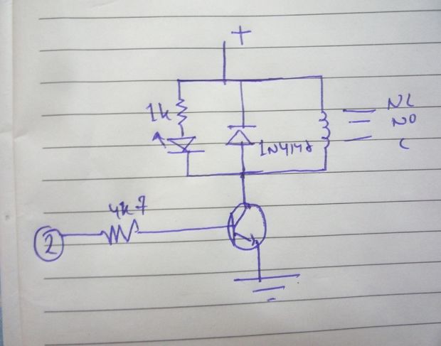
In this section, we will power or control the relay with the help of Arduino. You can connect the NO, NC and C accordingly as per the circuit diagram.
In the circuit, to the positive power supply, the positive terminal of the LED is connected through a 1k resistor; and the negative terminal of 1N4148 diode is connected and positive terminal of it is connected to negative terminal of the LED.
The coil of the relay is attached across 1N4148 diode's terminals. The BC547 transistor is connected to positive terminal of the 1N4148 diode and emitter is connected to Ground. Base is connected to pin no. 2 of Arduino through a 4k7 resistor.
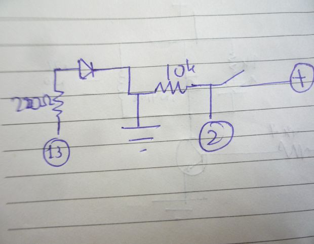
Debouncing a Button ShieldHere is the making of the "Debouncing a Button" shield. Sometimes we press a button, but it does not count in the counter. Even if you press 10 times, it can count only to 5 or 6 times. In bouncing, the contact of the switch is made only on one side and not both the sides, and then it contacts both the side. We will study the bouncing phenomena with the help of this shield.
In the circuit, we have a tactile switch connected across pin no. 2 of Arduino UNO and VCC. 10k resistor is placed across GND and Pin no. 2 of Arduino. 220 ohm resistor is connected to pin no. 13 and is connected to positive terminal of the LED, while the negative terminal of the LED is connected to GND. And there we have a complete Debouncing A Button Shield.
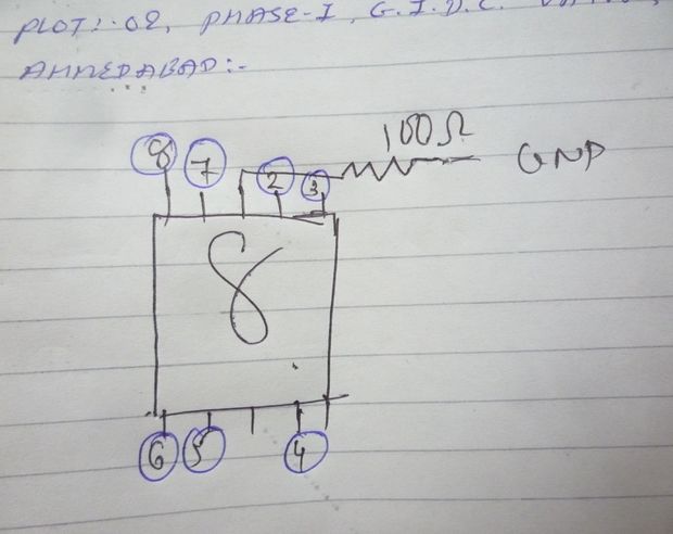
Seven Segment Display ShieldIn this section, we would try to Interface the Seven Segment Display to the Arduino. We will then, with the help of code, try to make a 0-9 Display.
The circuit diagram is in the schematics section. You can follow it.
Connections of Seven Segment Display are as follows:
- PIN 1 to PIN 6 of Arduino Uno
- PIN 2 to PIN 5
- PIN 4 C to PIN 4
- PIN 6 to PIN 3
- PIN 7 to PIN 2
- PIN 9 to PIN 7
- PIN 10 PIN 8
- PIN 3 to ground through 100Ω resistor.
Now our Seven Segment Shield is ready.
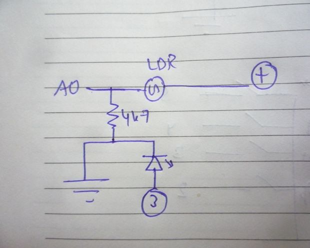
Light Sensing ShieldIn this section, light is sensed through LDR. In the circuit diagram, LDR is connected across A0 Pin and VCC of the Arduino. The negative terminal of the LED is connected to A0 pin through a 4k7 resistor and positive terminal is connected to pin no. 3 of Arduino.
Now our Light Sensing Shield is ready.
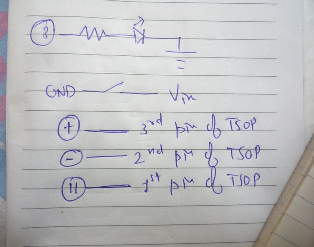
IR Communication ShieldNow we will interface the IR LED and TSOP to the Arduino. As you tap the switch IR LED will transmit IR Rays. TSOP does the work of the receiver. You can make the circuit by following the circuit diagram.
You can find the code here:
https://learn.sparkfun.com/tutorials/ir-communicat...
The positive terminal of the IR LED is connected to pin no. 3 of the Arduino through 100 ohm Resistor. A switch is connected between GND and Vin Pin of the Arduino.
- 3rd Pin of TSOP is connected to VCC of Arduino.
- 2nd Pin of TSOP is connected to -ve of Arduino.
- 1st pin of TSOP is connected to 11 pin of Arduino.
Now your IR Communication Shield is also ready.
D-Pad Button Sheild
UPPER BUTTON is connected to pin no. 2 of Arduino.
RIGHT BUTTON is connected to pin no. 3 of Arduino.
LEFT BUTTON is connected to pin no. 4 of Arduino.
DOWN BUTTON is connected to pin no. 5 of Arduino.
Seven Segment Display Shield
PIN 1 to PIN 6 of Arduino Uno
PIN 2 to PIN 5
PIN 4 C to PIN 4
PIN 6 to PIN 3
PIN 7 to PIN 2
PIN 9 to PIN 7
PIN 10 PIN 8
PIN 3 to ground through 100Ω resistor.
IR Communication Shield
3rd Pin of TSOP is connected to VCC of Arduino.
2nd Pin of TSOP is connected to -ve of Arduino.
1st pin of TSOP is connected to 11 pin of Arduino.


_3u05Tpwasz.png?auto=compress%2Cformat&w=40&h=40&fit=fillmax&bg=fff&dpr=2)
Comments